

You are using an out of date browser. It may not display this or other websites correctly.
You should upgrade or use an alternative browser.
You should upgrade or use an alternative browser.
Nelson Pass F5 build, Part Trois...
- Thread starter westend
- Start date

westend
Audiopile
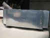
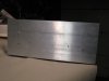
Thanks, the front sub-plate is bolted to the chassis on the sides and onto the bottom, using aluminum angle pieces. The top bolts onto those angle pieces, also. The faceplate will have 4 visible bolt recesses. It bolts through the sub-plate and into the chassis. The fifth and sixth holes are for the LED's.Looks great Lance!!
How did you attach the front plate to the chassis with no fasteners
visable??
Attachments
westend
Audiopile
Things look to be coming along great, Lance!
RC
Yep, Just about to take her for a dance, as soon as I get her back side back on. Still thinking about what to do with her top and face but I'm sure it will come to me. :nerd:
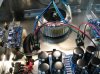
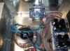
Inputs, speaker outs, and LEDs remain to be done before the music starts.
Ron, have you had an F5 on the JBL's, yet?
Attachments
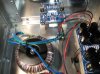
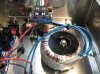
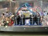
With the 100 ohm 3 watt blue panasonics, I had no choice but to go with the
"longer" holes.... What resistors did you use, or did you stand them up? I would have assumed the "shorter" hole would have worked, did you ask Peter about that?
I'll try to locate the post by Nelson about the feedback, I took notes during my read to try to simplify finding things during construction. I'll post pics of the stuffed boards.....
Russellc
I don't rememeber which brand of resistors I used, but I initially used the the wrong set of holes which ended up with both legs of the resistors being connected to the same trace. I would get bursts of oscillation at high volume. When I posted scope shots and pictures on DIYAUDIO someone saw my resistors and said they did the same thing, then someone else chimed in - so I figured I would share it over here.
I did not stand up those resistors, but all the other resistors I did stand up.

DENNYDOG
Addicted Member
Looking good Lance! Everyone should know that metalwork like this isn't as hard as it looks. A lot of the stuff can be done with basic tools most everyone has around their house. And those metal blades are the hot ticket aren't they?! We have a couple skillsaw style saws at work. Amazing that you can cut through 1/4" plate steel like butter. They will cut through 1/2" or thicker if your patient. 
westend
Audiopile
Yessiree, the Amana blade is a treat to use, Denny, and you're absolutely right about the ease of the metalwork. Anyone that has decent measuring tools, a drill, and is in any way practical, should be able to build a fairly nice chassis.Looking good Lance! Everyone should know that metalwork like this isn't as hard as it looks. A lot of the stuff can be done with basic tools most everyone has around their house. And those metal blades are the hot ticket aren't they?! We have a couple skillsaw style saws at work. Amazing that you can cut through 1/4" plate steel like butter. They will cut through 1/2" or thicker if your patient.
The standoff blocks are HDPE (high density polyethylene) that I had left over from making various slides and fences for woodworking tools. I followed Tal's lead on that and they worked out very well. The material is available at local woodworking stores like Rockler, Woodcraft, etc..Lance,
where did you source the white blocks that the pcb's are mounted on??
Update on the build: All is in place and wired (I did'nt have any light on the LED's and I may have to cjhange resistor value or might have the leads reversed. That segues into the initial startup process (regarding the "reversal" bit). I checked the AC values, DC values from the transformer, and the resistance of the trim pots and all looked good.
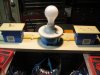
I hooked up the poor mans variac and stated to measure voltages. I had a value of .346v acoss R11 and R12 and, in hind sight, that should have let me know that something was amiss. But, since the value was lower than the operating value and I assumed it would not rise above .59, I let the amp idle with the bulb for an hour or so and then fired it up under full power. I was busy monitoring the rail voltages when I smelled that awful smell, yikes, R11 and R12 are HOT, HOT HOT. Hit the power switch and sat back for a moment. What could be the problem? Could I have mistakenly shorted something on the output side? Is something loose or a soldering mishap?
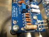
Here's what happened:The bourns trim pots are set so that the wiper is positioned to resist the current in the fully clockwise position. In my pea-brain I thought this was counter-clockwise. I powered the amp with full current enabled.:tears: I will replace the R11 and R12 resistors, turn down the trimpots and try for another go at setting the bias.I think I may have saved everything downstream in the amp circuits because I was able to power down quickly. The .047 3w resistors still measure in spec and the mosfets barely got the heatsinks warm. Hopefully, the Jfets are still OK. I do have thermistors attached to the cases and the current limiting is on the boards so I might have dodged a big bullet.
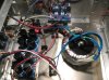
At least one Pass builder is able to share some drama and screwups. Attached are pics of the poorman's variac, the amp as it is built, and the smoked resistor.
Attachments

qboneus
Senior Member
I can't speak for Lance but 'I' threaded mine..Lance,
Are the standoffs threaded into the HDPE or glued??


Looks awesome Lance!!!
cheers,
tal
Last edited:

specialidiot
Break Glass, Smoke Lucky
Nice work Lance. I actually smoked one of my R11/R12 pairs too.
Regarding the stand0ffs, I understand the desire to mount the boards on something, and I actually communicated with some of the other builders on diyaudio.com about this. Most don't mount to a solid base, mostly because the board is so light that it's not needed. Many also contested that having the boards solidly mounted could cause trouble with added stress on the pads of the pcb. I argued that if you mount to the standoffs, then soldered it shouldn't matter.
But bottom line, my boards hang by the TO-220's from the heatsink. I run mine multiple hours per day, ever day for several months now without issues.
Regarding the stand0ffs, I understand the desire to mount the boards on something, and I actually communicated with some of the other builders on diyaudio.com about this. Most don't mount to a solid base, mostly because the board is so light that it's not needed. Many also contested that having the boards solidly mounted could cause trouble with added stress on the pads of the pcb. I argued that if you mount to the standoffs, then soldered it shouldn't matter.
But bottom line, my boards hang by the TO-220's from the heatsink. I run mine multiple hours per day, ever day for several months now without issues.

Russellc
Addicted Member
Nice work Lance. I actually smoked one of my R11/R12 pairs too.
Regarding the stand0ffs, I understand the desire to mount the boards on something, and I actually communicated with some of the other builders on diyaudio.com about this. Most don't mount to a solid base, mostly because the board is so light that it's not needed. Many also contested that having the boards solidly mounted could cause trouble with added stress on the pads of the pcb. I argued that if you mount to the standoffs, then soldered it shouldn't matter.
But bottom line, my boards hang by the TO-220's from the heatsink. I run mine multiple hours per day, ever day for several months now without issues.
Many have done the Daniel's boards in a similar fashion. The mosfets are against the heat sink, with legs bent 90 degrees so they stick out. Board is lowered onto the legs and soldered in place, with board hovering over the heatsink, held in place by the pins and solder. Likely how I'll do mine, plus it doenst use any real estate up inside the case.
Russellc
westend
Audiopile
I press-fit and glued the nylon posts into the blocks. I used a two-part epoxy to glue them to the chassis bottom.Lance,
Are the standoffs threaded into the HDPE or glued??
Jeff, that takes a little of the sting out of my "senior moment", knowing I'm not the only one that screws up
.Hanging the boards should work out OK. The legs on the mosfets are pretty sturdy. It sure makes for easier removal, if needed. I just am an old sailor, at heart, and tend to overbuild and secure everything, don't know what kind of weather is coming.:worried:
I still need some time to asess my stock of resistors and measure the ones on board that are all toasty. I might venture a restart.
westend
Audiopile
Muhahaha...it lives!
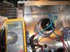
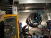
Must have been a Halloween thing going on :arrow:, all is now good. Voltages are fairly stable and DC offset is almost non-existent, .000-1 DCV.
I guess a Haiku is in order for NP: Simple and sweet amp
Silence hardly warms the soul
Waiting to enjoy
I'l let her run for awhile and keep an eye out for any drifting. It's been fully powered for about three hours and is barely warm, I could leave my arm or hand on there indefinitely. I think the all aluminum case is a good idea. I can see that the whole case is acting like a heatsink, the back, front, and bottom are all just slightly warm.:thmbsp::thmbsp:
Must have been a Halloween thing going on :arrow:, all is now good. Voltages are fairly stable and DC offset is almost non-existent, .000-1 DCV.
I guess a Haiku is in order for NP: Simple and sweet amp
Silence hardly warms the soul
Waiting to enjoy
I'l let her run for awhile and keep an eye out for any drifting. It's been fully powered for about three hours and is barely warm, I could leave my arm or hand on there indefinitely. I think the all aluminum case is a good idea. I can see that the whole case is acting like a heatsink, the back, front, and bottom are all just slightly warm.:thmbsp::thmbsp:
Attachments
specialidiot
Break Glass, Smoke Lucky
Well done Lance!
Enjoy the music....
Enjoy the music....
westend
Audiopile
Well done Lance!
Enjoy the music....
Thanks, Jeff for leading the way on these F5 builds. I could not have done it without your thread and Tal's help. It is actually a pretty easy project, as Nelson put it, "So easy a Geico customer could do it". But your thread and Tal's were referenced many times.
I plan on hooking up the Yamaha C-2A and the Plant Hangers to see what this sweetheart can do.
On a side note, I was talking to an anodizer, a few days back, and he seemed to think he could run a few pieces for me for pretty cheap. I'm really getting used to the polished aluminum look and may keep everything but the faceplate and top in it's polished state. Maybe throw a coat of laquer or some such on the polished stuff and get a silverish-grey/black anodizing on the top and face. That might blend between the silver and black gear and approach the Kenwood Euro anodize that I really like.
Attachments
Last edited:

thefragger
Certified Crazy.
Excellent!
That looks great! Now what about a face, Lance?? :scratch2:
That looks great! Now what about a face, Lance?? :scratch2:
westend
Audiopile
Thanks!Excellent!
That looks great! Now what about a face, Lance?? :scratch2:
I've got some work to do on the faceplate. My current plan is machine an edge on face, finish process the six surfaces, see if I can get an "F5" graphic of some sort, and meet with the anodizer to see if he can apply a tint to meet my choices. I'll be firing up the router, this evening, to see what I can accomplish.
Hey Russel,That's great westend, Icant wait to fire mine up. I'll remember to double check the pot settings before hand. I do have a variac, so that may ease the problem. Hook that beast up to some speaks!
Russellc
I used the "poor man's variac", the 100w bulb device. Unfortunately, it was the first time I used it so I didn't know how it would limit current. I did know that it would show if I had a short and since all was good and no shorts I proceeded to full power. Within a few seconds, I realized all was not good and I flipped the switch to save the components from damage.
I had measured the trimmers before installation (this is really the best way) but trying to measure the resistance value in circuit does not lead to accurate results. I was relying on past information so I turned the wiper fully counter-clockwise. That is wrong!The 5k Bourns pots are zero'd by turning clock-wise.
A variac, of course, is the best choice, and I have been looking for one for reasonable price. Heck, I have an Oscope that just arrived and haven't had time to put it through the paces. A man can't have enough tools is my motto
.I will, hopefully, have the F5 hooked up to listen, tonight. Will report back with results.
Russellc
Addicted Member
Depends on which boards you are using!
As to the pots, there is a difference in the Cviller and Daniels boards. they connect different legs together a little differently than each other, resulting in OPPOSITE results. One results in minimum reading counter clockwise, the other clockwise. There is a very recent post on the F-5 thread over on DIY.
Russellc
Thanks!
I've got some work to do on the faceplate. My current plan is machine an edge on face, finish process the six surfaces, see if I can get an "F5" graphic of some sort, and meet with the anodizer to see if he can apply a tint to meet my choices. I'll be firing up the router, this evening, to see what I can accomplish.
Hey Russel,
I used the "poor man's variac", the 100w bulb device. Unfortunately, it was the first time I used it so I didn't know how it would limit current. I did know that it would show if I had a short and since all was good and no shorts I proceeded to full power. Within a few seconds, I realized all was not good and I flipped the switch to save the components from damage.
I had measured the trimmers before installation (this is really the best way) but trying to measure the resistance value in circuit does not lead to accurate results. I was relying on past information so I turned the wiper fully counter-clockwise. That is wrong!The 5k Bourns pots are zero'd by turning clock-wise.
A variac, of course, is the best choice, and I have been looking for one for reasonable price. Heck, I have an Oscope that just arrived and haven't had time to put it through the paces. A man can't have enough tools is my motto
I will, hopefully, have the F5 hooked up to listen, tonight. Will report back with results.
As to the pots, there is a difference in the Cviller and Daniels boards. they connect different legs together a little differently than each other, resulting in OPPOSITE results. One results in minimum reading counter clockwise, the other clockwise. There is a very recent post on the F-5 thread over on DIY.
Russellc
Russellc
Addicted Member
As to the pots, there is a difference in the Cviller and Daniels boards. they connect different legs together a little differently than each other, resulting in OPPOSITE results. One results in minimum reading counter clockwise, the other clockwise. There is a very recent post on the F-5 thread over on DIY.
Russellc
Whoops, I see you have already been there and that advice may be in question, sounds like maybe they have it backwards? I have the daniels boards, so I need to find out....
Russellc