• The move to the new server is done. There are some software and database maintenance updates in process. This has us passing the hat around to help out. We appreciate any donations. Seriously, even a dollar helps. The payment page may be found here - https://www.audiokarma.org/support.html

Pioneer M-22; Worth a Repair Attempt?

It has not passed the DBT on 150w. The bulb remained bright for about a minute or so and then I turned it off. But since the power consumption of this thing is like hundreds of watts during normal operation (and presumably the current draw is much higher on startup) wouldn't a bulb of like 60w glow regardless? I'm still new to this whole DBT thing so apologies if these are dumb questions.
These are not dumb questions! The dbt protects the internal parts of the amp by limiting power to the unit under test, if the amp tries to draw too much power the bulb limits it so no more power can flow through the amp than the bulb would dissipate by itself. As the power supply caps charge at power on the bulb flares bright, but limits the current. When the caps are charged the power draw diminishes and the bulb dims. If the bulb does not dim it indicates that more power is still being drawn. On a large amp a 60 watt bulb may indeed glow after the caps are charged, so increase it to a 100 watt bulb, or more. That one should be dimmer, but still protect the amp. If the bulb does not dim you still have a problem, because a normal amp that is not making music only draws a few watts during idle condition. It only draws large amounts of power when outputting loud music, especially with heavy bass. Think about it like a car engine, when it is idling it only uses a little bit of gas and won't move the car at more than a walk, if at all. When you step on the throttle (turn up the volume) it takes more gas and puts out more power. Even a huge gas guzzler engine does not use much gas at idle, even though it has the potential to put out huge amounts of power at full throttle. The dbt limits the flow of 'gas' so the engine will not over-rev without a proper load. Sorry if that is too much info :rolleyes:.
You can set dc offset on dbt and it will be close to where it should be. You can test the bias on dbt for adjust-ability to check function, but must reduce it to minimum or risk it being to high on full mains voltage. Then set it correctly on full power.
 
If I'm reading the service manual correctly, the idle current draw of the M-22 is 1.7 amps at the power cord (this number is on page 13). Seems to suggest that even at idle it may fully light the 150w bulb.
 
T
If I'm reading the service manual correctly, the idle current draw of the M-22 is 1.7 amps at the power cord (this number is on page 13). Seems to suggest that even at idle it may fully light the 150w bulb.
That spec you are seeing is the idle current for the power amp output stage, not the AC input. However, I had neglected to consider this is a Class A amp so the power dissipation is virtually the same at no load and full load. My bad. So you are correct about the idle dissipation being high, about 200W, but the UL power consumption spec on page 2 is 280W. Try it with a higher wattage bulb, or two in parallel. Never the less I would still should check that the adjustments do adjust and that the power supplies are balanced (+/-) with 300W in the dbt.
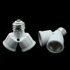
Two 150W bulbs in one of these should work:
41DZyrwhHkL.jpg
 
Great idea, I'll order one of those dual bulb holders. Another question: how bad is it to run without the soft start? The service manual keeps mentioning that only the KL type has it; why would there be a version without soft start if it's necessary to preserve the rectifiers and power switch? Seems odd. All I can think of is that Japan has 100v, but the difference between 100 and 120 doesn't seem significant enough to account for it.

Anyways, I'm assuming the DBT acts as a soft start, so I'm probably safe on that. My current plan is to check it on DBT with 300w, then (assuming it passes) run it once on full mains to make sure it's working before I attempt any further repairs. If I get a good result on mains then I'll probably shelve it until I have time for a full rebuild (soft start, caps, relays, trimmers, and maybe some of the dodgier low power transistors).
 
You are correct, the dbt does basically the same thing as the soft start: provides a ballast to limit current. It just stays in the circuit, rather than being switched out by a relay. On the lower ac voltages (KL, US model) the transformer primary start current is much (2x+) higher than the 220 volt amps (N, General Export models). The secondary side currents are the same. IF the power switch, rectifiers and transformers were spec'ed to handle the current it is ok, but the presence of the relay and the cut wire stubs makes me think somebody modified your unit. Who knows, that may be why your amp died. :dunno: Soft start reduces long term component stresses.
Just remember to check dc offset and bias function before going to full mains.
Looks like you are on the right track! :thumbsup: :cool:
 
Ok, so I tried it on the 300w dbt and still no luck. Or at least no speaker protection relay activation. I suppose I need to bite the bullet and take out the amp boards; I've been trying to avoid that since I'm low on time but it's looking necessary. For what it's worth, I measured DC voltage across the main filter caps right after shutting it down and got 0-4v (depending on the cap). I had the leads alligator clipped to one of the caps while it was powered on and the reading was about 4.3v. Shouldn't these be at like 30v? I'm guessing this points to a power supply issue?

Also @reddish75 thanks a million for that link; somehow I never stumbled across that page. Looks like a great way of replacing the bridge rectifiers. I found the ones he used on Ebay, but I'm wary of counterfeits.
 
Ok, so I tried it on the 300w dbt and still no luck. Or at least no speaker protection relay activation. I suppose I need to bite the bullet and take out the amp boards; I've been trying to avoid that since I'm low on time but it's looking necessary. For what it's worth, I measured DC voltage across the main filter caps right after shutting it down and got 0-4v (depending on the cap). I had the leads alligator clipped to one of the caps while it was powered on and the reading was about 4.3v. Shouldn't these be at like 30v? I'm guessing this points to a power supply issue?

Also @reddish75 thanks a million for that link; somehow I never stumbled across that page. Looks like a great way of replacing the bridge rectifiers. I found the ones he used on Ebay, but I'm wary of counterfeits.
I am beginning to wonder if this amp, being class A, will always have a bright dbt bulb, because it dissipates full power all the time, it just dissipates it from the heat sinks when sitting idle, and cools off when the speakers are being driven. I would like to hear from someone who has one if they used a dbt on it?
If you were measuring across the big filter caps, there are 8 of them, 2 for each channels' output +/- supply (33,000µF monsters), and 2 for each channels +/- non-output supplies (1000µF), I would expect more than 4.3vdc. Measure the voltage across the TP test points to see if there is excess current flowing through the outputs. At full voltage the 'idle' current is 1.7A or 850mVdc on the test points. If the dbt is choking it too hard to let the power supplies come up the relay will never pull in. Have you tried powering it up with all 8 output transistors removed? That would eliminate the high idle current and allow troubleshooting the rest of the circuits.
 
@merlynski I'm also beginning to wonder whether the DBT simply isn't useful with this thing, and I'm finding posts saying that DBTs don't generally play well with big Class A amps. I'm tempted (again) to throw it on mains, especially since I checked all the outputs and they were good. I'd almost rather take the small risk that mains nukes something than spend dozens of hours poking around only to realize it's the DBT stopping the relays from activating. It does have a fuse, so at least it won't go nuclear on me. All I want is to hear it play music so I can be sure it works and begin the SS rebuild.
 
Also found this quote from a while ago:

I've been using a DBT regularly for almost 10 years and it has saved my ass many times...sure...my Pioneer Series 20 M25's won't power up on a DBT due to the 90 mV bias voltage, but everything else from new-to-me-unknown-condition SS amps to recap's and semiconductor repairs are powered up first on the DBT. Saved a few unobtainium output transistors from smokin' and worth its weight in blown fuses.

The DBT has been a huge confidence builder and safety net. Like EW says, you do need to understand the tools you are using, but anyone attempting repairs on the gear we talk about on this forum needs to take an analytical and calculated approach anyway.:yes:

Given the similarities between the M-25 and the M-22, I'm guessing the M-22 probably won't power up on the DBT either.
 
avionic makes a good point, look it over carefully for other "modifications."
If it were mine, at this point I would repair/replace the soft start circuit and then give it a try without the dbt. Another alternative would be to have a bypass switch on the dbt bulb, power it up on dbt, then bypass it to go the rest of the way to full mains.
If you have two dmms you could monitor the idle current tps on both channels throughout the process and see what it is drawing.
 
I think I'm going to bite the bullet and rebuild the SS this weekend before going any further. It shouldn't be difficult and it needs to be done eventually anyway. The contacts on the original SS relay look pretty severely burnt, so no surprise it was bypassed.

I've got a parts list ready, but I do have one question. In the link posted by reddish above, the repairer used G4W-1112P-US-TV8-HP-DC24 relays, which appear to be pin-compatible with the original Omron MU2 24VDCs. However, in the big SBAF thread, the repairer used TE Connectivity relays, which he claims are the only directly equivalent relays you can buy. Obviously, something doesn't add up here, and I'd be interested in any opinions. Are the G4W-1112Ps fine or is the SBAF guy right? I tried looking into it but my understanding of relay minutiae is not nearly adequate.

Also, regarding diode replacement: I plan on using the SBYV28-200-E3/54.
 
Oh, and one other question: any way of figuring out what D1 in the SM is? It's supposed to go across the pins of the SS relay, but whoever worked on this thing removed it. Unfortunately, the SM only lists the Pioneer replacement part number. I'm looking at the equivalent diode on the protection relays but all the package says is "0476:" and I don't know what to make of that. Could I just replace it with a generic 1A diode?
 
Oh, and one other question: any way of figuring out what D1 in the SM is? It's supposed to go across the pins of the SS relay, but whoever worked on this thing removed it. Unfortunately, the SM only lists the Pioneer replacement part number. I'm looking at the equivalent diode on the protection relays but all the package says is "0476:" and I don't know what to make of that. Could I just replace it with a generic 1A diode?
Yup a generic 1n4004 would work fine.

I've got a parts list ready, but I do have one question. In the link posted by reddish above, the repairer used G4W-1112P-US-TV8-HP-DC24 relays, which appear to be pin-compatible with the original Omron MU2 24VDCs. However, in the big SBAF thread, the repairer used TE Connectivity relays, which he claims are the only directly equivalent relays you can buy. Obviously, something doesn't add up here, and I'd be interested in any opinions. Are the G4W-1112Ps fine or is the SBAF guy right? I tried looking into it but my understanding of relay minutiae is not nearly adequate.

I looked at the datasheet for both relays you mention. The G4W-1112P-US-TV8-HP-DC24 is rated at nominal 10 amps for switching current, and 15 amps for max switch and carry current, the relay in the SBAF thread is rated 3 to 7.5 amps with a resistive load, and is listed as a Signal relay not a power relay. I would go with the G4W-1112P-US-TV8-HP-DC24, it has a much more robust contact rating.
 

Attachments

Before you go diving into this, have a good think whether you are confident you at least have the skills to solder and desolder correctly. The power amp boards if they look like the link I posted will have extremely brittle solder pads which without great care will break off.

Use good quality desolder braid, and a temperature controlled station.

Do not buy any parts of ebay no matter how tempting, just stick to the large part suppliers.

For the diodes 1N5402 - 1N5408 will work, maybe invest in one of those plastic component lead benders and mount them raised above the board.

On the link I don't like the way he's mounted those capacitors. Use axial ones like the vishay mal series and use high temp ones
 
Last edited:
markthefixer recommended 653-LY2-DC48 for the soft start relay, from Mouser, if the original is 48vdc.
 
Back
Top Bottom