• The move to the new server is done. There are some software and database maintenance updates in process. This has us passing the hat around to help out. We appreciate any donations. Seriously, even a dollar helps. The payment page may be found here - https://www.audiokarma.org/support.html

Pioneer M-22; Worth a Repair Attempt?

Alex: 24v on all three relays?
The 120v model has the SS relay, in the center.

Please double check.

The other two (outer) relays are the protect relays - one for each channel.
They are connected to the raw DC 28v - thus we know what they are operating at.
And that they ARE 24v relays. With a few extra diodes for the couple of volts to be dropped.
 
Yes, 24v on all three relays, including the center one. In fact, all three appear to be the exact same model of relay.

In other news, I removed the amp board with the power supply (AWK-058) and luckily I don't see any modifications. Everything looks stock, no catastrophic failures of parts that I can see, although a few caps do appear to be mildly bulging. The whole board feels way too light for what's on it, so I'm guessing the electrolytics have dried out a bit. I think I'm going to follow skem from SBAF's strategy -- high-temp Vishay for the big axials and polymer caps for the smaller radials. Normally I wouldn't go around adding polymers but since he already went that route with no issues I'll probably follow suit. However, I'm not planning on replacing all the ceramics like he did.
 
About to submit the Mouser order, but I have another question: is replacing the original film caps in the signal path (a 1uf and a 3.3uf afaik) worthwhile or snake oil? The SBAF poster claimed he heard a difference and measured some slight changes in distortion when these were upgraded to modern film caps. However, I've heard many people say that all film caps are basically good and there's no point messing with them. In the end, it would only cost a few bucks to replace them, so I'm leaning towards giving it a try. However, I'd love to hear any opinions.
 
newer metallized film caps have wide connection areas on the flat sides of the roll, short straight paths ONLY to the side connections.
older caps were more like toilet paper rolls with a connection on the foil, current going out of the caps had to travel the spiral paths - and that's called parasitic inductance.

from wikipedia:
A key advantage of modern film capacitor internal construction is direct contact to the electrodes on both ends of the winding. This contact keeps all current paths to the entire electrode very short. The setup behaves like a large number of individual capacitors connected in parallel, thus reducing the internal ohmic losses (ESR) and the parasitic inductance (ESL). The inherent geometry of film capacitor structure results in very low ohmic losses and a very low parasitic inductance, which makes them especially suitable for applications with very high surge currents (snubbers) and for AC power applications, or for applications at higher frequencies.
 
Last edited:
@markthefixer thanks for the great explanation.

So I went ahead and submitted the order; gonna be an expensive restoration but I love this thing so it's worthwhile. I pasted the BOM into a shareable Google Sheets file so that if anyone else with an M-22 stumbles across this thread they can have another point of reference. Of course, no guarantees my decisions were the best ones. I also enabled commenting so you can tell me if I'm an idiot. Here's the link: https://docs.google.com/spreadsheets/d/1Gcudf4qij3hUQxGfHdfeNcOx5FzJasgYDHeN6mzzg18/edit?usp=sharing
 
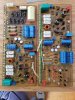
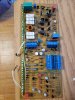
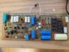
Got around to fully restoring the amp boards today. Replaced all the electrolytic caps and a few of the film and ceramic ones as well. Also replaced the offset/bias trimmers and the beefy diodes in the main bridge rectifiers. However, it's gonna be a while longer before I can try firing it up again; still need to replace the relays and redo some of the wiring that was removed. By far the most difficult part of the board restore was sanding down the leads on the big yellow film axial and getting it to fit. Also, the Bourns trimmers I got have the opposite lead configuration of the old trimmers, so I had to do some crafty lead bending and even then they barely fit. I'm worried about whether I'll actually be able to turn them once it's mounted given their leads were thin to start with and have now been contorted quite a bit, but I guess we'll see.

Anyways, see below for a bunch of pics! Apologies for the varying orientations -- I always forget to take my pictures properly when I'm caught up in the work.

Before:

20191109_003720.jpg

After:

20191109_150553.jpg

20191109_143047.jpg

20191109_143120.jpg

20191109_143143.jpg
 
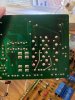
People expressed concern about the PCBs but they ended up being fine. Didn't have issues with pads lifting or anything. For some reason they were a bit scratched up before I worked on them (a lot of the scratches in this image were there before), but nothing that would impact the traces.

20191109_151148 (1).jpg
 
The saga continues! Set aside tonight and tomorrow for working on the M-22 -- hopefully enough time to finish it. Next item on the list is relay replacement. Just replaced the soft start relay, which the previous owner had removed entirely, and redid all the wiring. The pics on the internet are of 100v M-22s with a slightly different layout, so I had to work from the schematic. Perfect opportunity to brush up on my lackluster circuit tracing abilities. The wiring could have been routed better -- oh well. I ran out of wire due to a cheap stripper that only seems to cut on one side.

Next on the list: replacing speaker protection relays. None of my replacement relays match the originals, so I'm going to need to drill some Lexan covers to hold them in place. Then it's just polishing the contacts and setting bias/offset and it'll be ready for action (hopefully). The replacement bias and offset trimmers have really flimsy leads so I'm planning on hot glueing them in place.

Pics:
20200118_193039.jpg

20200118_194431.jpg

20200118_193103.jpg
 
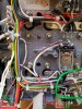
Another update: yesterday I finished all the remaining work. Fashioned some Lexan pieces to hold the relays in place, polished the pins, and reassembled everything. Unfortunately, my DBT is no longer with me (left at home) so I brought it up normally. The LED installed by a previous owner lit up, but I'm not sure whether the main relay tripped because I was distracted by something else: magic smoke! It was a small amount and the fuse didn't blow, but there was definitely some smoke coming from the right channel. Based on a cursory visual inspection, I think it was coming from R2 and R3, which are small 1/5w resistors right above VR1. I'm also fairly certain that the speaker protection relay didn't trip on either side, which would indicate I have an issue with DC offset (or my wiring of the new relays).

My plan for next weekend is to pull the board out, give it a visual inspection, test those two resistors as well as the other parts nearby, and stare at the schematic for a while. I'm guessing I should also probe the power supply rails to make sure it's not nuking everything? Any tips would be appreciated -- I'm not exactly sure where to look.

Another question: is there a best practice for setting the offset and bias trimpots before turning it on? I pretty much installed them as they came, figuring I would just set everything once it was on, and the service manual doesn't specify what position they should start in (as far as I can tell).

Phone is being weird right now so I'll upload the pics later.
 
Another question: is there a best practice for setting the offset and bias trimpots before turning it on? I pretty much installed them as they came, figuring I would just set everything once it was on, and the service manual doesn't specify what position they should start in (as far as I can tell).

Yes, center the dc offset pots (VR1s), and set the bias pots (VR2s) for minimum bias (minimum resistance with ohmmeter) before powering it up again. If the bias is set too high on power-up the magic smoke will escape. Check the power supplies' voltages before trying to set dc offset or bias.
 
Ok, I'm back at it. Removed the boards, luckily I don't see any visible damage. One resistor looks like it might have overheated, but still measures within spec. I'm going to properly set all the pots this time around, thanks @merlynski. Another question -- when I tried it earlier, I didn't get any relay activation. Would it be beneficial to test with outputs disconnected and see if the power relay clicks properly? If I go this route, should I use the DBT or not? Cheers
 
So I just measured the values of all the trimmers. Both VR2 trimmers are working as expected. They were ~55 ohms during my first run but I've set them to .5. However, my right channel VR1 seems broken -- perhaps that's what was smoking. Resistance between pins 1 and 3 is normal (101 ohms) but between the wiper and either pin is like 5 Mohms and climbs the longer it's measured, so I assume the wiper is no longer connected to the track. On the left channel, VR1 operates as expected.

I'll order a new VR1 trimmer for the right channel before doing any further testing. I'm wondering if it would be smart to get a higher-wattage trimmer; I think the Bourns multi-turn ones I'm using are 1/5w or something.
 
You can test your amp with the outputs removed. Since the driver transistors emitter resistors connect to the output/negative feedback node the amp will 'dc balance' without drawing large currents through the output transistors. If you put a 500 to 1K Ω jumper resistor in place of each of the removed output transistor's BE junctions (i.e. pin 5 to pin 6, pin 5 to pin 7; pin 13 to pin 12, pin 13 to pin 11) you will get a 'closer to real' test. You can verify that dc offset and bias are adjustable in that condition. Be sure you set the bias adjustment back to minimum before installing the outputs and powering on, and use the dbt. Once the power supplies voltages are all functioning within tolerance you can skip the dbt in this test mode. The protection circuit relay should pull in when in this test mode since the Class A continuous current flow will not be flowing, and the dbt will not act/intrude as a ballast.
Caveat: I have not tried this on an M-22, but have done it and seen it done on other similar architecture (class AB) power amps.
 
@merlynski Thank you so much for the help! That test procedure sounds like a great way to proceed. One question -- what wattage should the jumper resistors be?
 
@merlynski Thank you so much for the help! That test procedure sounds like a great way to proceed. One question -- what wattage should the jumper resistors be?
1/2 watt should be plenty, even 1/4 watt should be ok, they are not there to carry a load, just to help close the DC feedback loop better.
 
Back
Top Bottom