• The move to the new server is done. There are some software and database maintenance updates in process. This has us passing the hat around to help out. We appreciate any donations. Seriously, even a dollar helps. The payment page may be found here - https://www.audiokarma.org/support.html

Pioneer M-90 Issue- need help.

In my last post above I mentioned the wrong resistor- I said R139 but meant to say R159. Anyway, I replaced that as well as checked all the diodes and transistors on the right channel PCB- a few resistors too. Noting checked bad. Put it back together and fired it up. Still getting that hum so back to the drawing board. I'm thinking I need to go back and figure why I'm reading resistance between chassis ground and the outer shell of the input jacks. According to the buffer amp schematic above- that should be a direct short (0 Ohms). Thoughts?
 
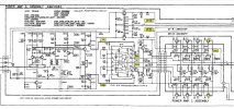
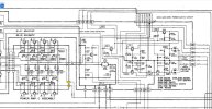
Just as a reminder- the unit appears to work fine with the exception of the hum that recently appeared on the left ch. I can confirm now the L-Ch heatsink does heat up quickly after start up which was not the case until after this hum issue showed up- both channels heated equally before. Proceeded with checking some voltages which are highlighted on the attached excerpt from the schematic. The voltage going to Q129/131 from the power supply is right around 65V and that's the same for both channels. Output of those 2 transistors going to the buffer amp is about the same for both channels although the schematic says it should be +/-76V. On the L-Ch, emitter of Q7 is -78mV and Q15 is +96mV and close to the same at pins 10 and 12 of the IC. According to the schematic, that should be 24mV. On the R-Ch Q8 emitter is -34mV and Q16 +48 mV. Not correct, but I'm not having issues with that channel. Any thoughts on where to look? I did pull every diode and transistor off the power amp "A" circuit card and checked with my relatively inexpensive component tester which did not indicate any issues. I can't remember if I checked all the fusible resistors on the power amp "C" card, but definitely checked some as well as took a hard look and didn't notice any issues.

1770488557664.jpeg
 

Attachments

  • Amp Section 2.JPG
    Amp Section 2.JPG
    117.7 KB · Views: 4
hum that recently appeared on the left ch. I can confirm now the L-Ch heatsink does heat up quickly after start up
this is starting to sound like a feedback loop (high frequency oscillation injection, possibly not) now exists and is loading down the channel, in an unhealthy fashion. or a fractured ground connection in the signal chain somewhere or... low value resistor has gone high. and yet it could be something simple to make a complex mess.

no idea if its one of the engineering quirks for the pioneer but an example of design flaw self destruction would be kenwood L-07m mono block (first thing that comes to mind for me).


*wire routing crucial, for the kenwood example. maybe m-90 has similar quirk if all else fails. this is probably and extreme out in left field guesstimation though.

*pardon the brand hijack, pioneer vs kenwood type of thing.

definitely post measurements and updates even if the problem persists. it will be helpful for any and all readers for years to come hence the value of an online forum (favorably maintained and nurtured though sickness and in health, @grumpy & team, ftw = for the win).

 
this is starting to sound like a feedback loop (high frequency oscillation injection, possibly not) now exists and is loading down the channel, in an unhealthy fashion. or a fractured ground connection in the signal chain somewhere or... low value resistor has gone high. and yet it could be something simple to make a complex mess.

no idea if its one of the engineering quirks for the pioneer but an example of design flaw self destruction would be kenwood L-07m mono block (first thing that comes to mind for me).


*wire routing crucial, for the kenwood example. maybe m-90 has similar quirk if all else fails. this is probably and extreme out in left field guesstimation though.

*pardon the brand hijack, pioneer vs kenwood type of thing.

definitely post measurements and updates even if the problem persists. it will be helpful for any and all readers for years to come hence the value of an online forum (favorably maintained and nurtured though sickness and in health, @grumpy & team, ftw = for the win).
A lot to absorb there and I'll need to dig into that. In the meantime- I'm guessing the 24mV off the emitter of the power transistors is the bias? If that's the case, what circuit/components control that? I figure that's at least got to be part of the problem. Even the right channel is high, but nearly 100mV on the left is excessive at the least.
 
A lot to absorb there and I'll need to dig into that.
yeah, my guessing probably doesnt help much since it adds another diagnostic vector which creates more confusion (my error).

24mV off the emitter of the power transistors is the bias?
correct, some manufacturers use a single resistor voltage drop others, sometimes, have tried using a voltage across two emitter resistors for upper and lower dc at the same time. single resistor measurement helps to identify if a particular output has a deviation or issue or dysfunction which makes root cause diagnostics easier.

component tester which did not indicate any issues.
unfortunately with vintage gear and the components contained within, faulty components can test ok since they are unloaded or not being electrically stressed like what the circuit design inflicts upon them. "when in doubt, change it out" sometimes helps since it reduces the amount of "aged" variables which have a high probability of needing to be updated/upgraded/replaced anyway. its a slow way of figuring out a system anomaly but it has a greater learning value (return on investment) which makes future diagnostics easier i.e. initial learning curve already conquered = more familiarity = comfort-zone established.

back to the task at hand, since the chip plays a considerable roll in setting/controlling bias it can be a prime suspect for circuit dysfunction. something that still needs to be evaluated prior to blaming the chip would be isolating the front end of the chip circuit to see if the integrated circuit of interest is acting or reacting. comparing voltage measurement on the chip input pins should be sufficient for initial analysis.

if there is some sort of stray signal or compromised ground or something that is generating a hum (unwanted signal at idle) upstream that would cause the chip to react which in turn loads the amp as it was designed to react. which in turn causes the bias to rise.

if... the chip has an age related issue and there is some sort of stray input noise or voltage/current leakage internally sourced then... its the chip. ic/integrated circuits are a big mystery box that can go in just about any direction without warning.

i will try to review the schematic again plus your updated measurements to see where the gremlin is hiding. if the r-ch is functioning normally it can be used as a temporary "known good" reference for voltage checks even though it is also aged and will have tolerance deviations of its own.

i seemed to have typed a book and the carpal tunnel is not amused, break time.

to quote the original tron movie: "end of line".

 
*might have some useful diagnostic tips/numbers in regards to the pa0016 troubleshooting
 
looking at the schematic, q15 upper (+dc rail) and q7 lower (-dc rail) so +24mv should be complimented by -24mv on the other emitter resistor, as a theoretical reference point vs real world measurements. the variance of R-ch +48mv/-34mv for the known-good channel helps to show what magnitude or normal circuit mismatch the system finds acceptable. can be used as a comparison starting point.

L-ch equivalent components measured +96mv/-78mv which appears to be double or close to it, interesting indeed. something is rev'ing the motor, what gremlin has their foot on the gas pedal i wonder.

i suppose a quick but somewhat dangerous test method would be to desolder both channels pa0016 chips, possibly install sockets to make diagnostics easier, and swap the chips to see if the high dc bias also follows. unfortunately that procedure runs the risk of damaging something on the known-good channel.

just a thought.
 
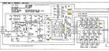
Checked voltages at a few more spots on the PWR Amp "A" Assy for both channels (near the red marks on the attached) and tell me what you think. IC101 pins 9 and 13. L-Ch 1.71V and 1.8V; R-Ch 1.84V and 1.88V. Then emitter of Q123/125 on the L-Ch- 123 .68V and 125 -.65V. On the R-Ch Q124/126 emitters- 124 .63V and 126 -.61V. Are those close enough to say the high bias voltage issue is not on that PCB and is likely on the PWR Amp "C" Assy?

1770581319205.jpeg
 

Attachments

  • Amp Section 2.JPG
    Amp Section 2.JPG
    117.9 KB · Views: 3
L - p9/p13 1.71v/1.8v
vs
R - p9/p13 1.84v/1.88v

there is a noteworthy different especially since these feed a transistor base (through a 100r each) but the q123/q125 vs q124/q126 emitter's seem to be tolerant of such a variance.

0.68/-0.65 vs 0.63/-0.61 should be close enough to not be an issue of immediate concern.

looks like there are several 4.7r resistors in the circuit path after the q123/q125 prior to reaching the output transistor base. definitely need to measure base voltage of each output transistor since that will determine action vs reaction.

one possibility, if the 4.7r are ok, would be to replace them with new/fresh resistors so that there is one less variable. another possibility, if resistor upgrade has no effect, would be a potential tired output transistor that has aged out of tolerance of become noisy. typically over the age of 65 humans get noisier as well, not just an electronics thing.
 
L - p9/p13 1.71v/1.8v
vs
R - p9/p13 1.84v/1.88v

there is a noteworthy different especially since these feed a transistor base (through a 100r each) but the q123/q125 vs q124/q126 emitter's seem to be tolerant of such a variance.

0.68/-0.65 vs 0.63/-0.61 should be close enough to not be an issue of immediate concern.

looks like there are several 4.7r resistors in the circuit path after the q123/q125 prior to reaching the output transistor base. definitely need to measure base voltage of each output transistor since that will determine action vs reaction.

one possibility, if the 4.7r are ok, would be to replace them with new/fresh resistors so that there is one less variable. another possibility, if resistor upgrade has no effect, would be a potential tired output transistor that has aged out of tolerance of become noisy. typically over the age of 65 humans get noisier as well, not just an electronics thing.
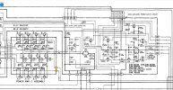
More info: Going back to that same schematic section above- to the lower right coming into the PWR Amp "C" board is 65VDC on terminal 111 and -65V on terminal 112. That voltage is the same on both channels and shows up on the base of all 8 power transistors (4+ and 4-), but on the left channel, all emitter voltages are high- anywhere from 70mV up to 100mV depending on the transistor. On the right channel the emitter voltages range from the 30s to the 50s (mV). Still high but that channel is not humming. Also, guessing the +/- 65V is the rail voltage? Schematic shows 67V (4ohm) or 82V (8ohm) but not sure what that means or how that's controlled. Any more thought on why the emitter voltage is so high across all those left channel power transistors? I've included more of the schematic to the right of the power transistors, but keep in mind the amp is NOT currently in protection mode and passes audio on both channels.

1770678022330.jpeg
 

Attachments

  • Overload.JPG
    Overload.JPG
    107.9 KB · Views: 2
65VDC on terminal 111 and -65V on terminal 112. That voltage is the same on both channels and shows up on the base of all 8 power transistors (4+ and 4-)
clarification request, are you referring to collector not the base for the rails +65v/-65v?

all emitter voltages are high- anywhere from 70mV up to 100mV depending on the transistor.
shows the channel is receiving a signal (circuit hum) and the outputs are reacting (sonic output if speaker attached) and heating up (thermal proof of channel loading/activity/bias increasing).

Also, guessing the +/- 65V is the rail voltage?
correct

Schematic shows 67V (4ohm) or 82V (8ohm) but not sure what that means or how that's controlled.
when the system has an output load (4r or 8r speaker)

design wise it looks like the pa0016 is being used as a dc bias servo which other brands/designs, like the primare multi channel amp i am finishing up with, use a dc servo for dc offset on the amp front end (to constantly maintain around 0mv). think of a dc servo circuit as an auto adjust/compensation mechanism, when needed, to maintain a particular voltage range.

if you have an oscilloscope, it might be possible to probe the circuit(s) from an ac (alternating current) point of view since so far we have been focusing on dc numbers. scope measurements for an ac voltage on all of the chip pins then compare the channels. best to float the scope for circuit safety, 2-prong mains adapter usually works.
 
clarification request, are you referring to collector not the base for the rails +65v/-65v?


shows the channel is receiving a signal (circuit hum) and the outputs are reacting (sonic output if speaker attached) and heating up (thermal proof of channel loading/activity/bias increasing).


correct


when the system has an output load (4r or 8r speaker)

design wise it looks like the pa0016 is being used as a dc bias servo which other brands/designs, like the primare multi channel amp i am finishing up with, use a dc servo for dc offset on the amp front end (to constantly maintain around 0mv). think of a dc servo circuit as an auto adjust/compensation mechanism, when needed, to maintain a particular voltage range.

if you have an oscilloscope, it might be possible to probe the circuit(s) from an ac (alternating current) point of view since so far we have been focusing on dc numbers. scope measurements for an ac voltage on all of the chip pins then compare the channels. best to float the scope for circuit safety, 2-prong mains adapter usually works.
Again, your time is much appreciated! Yes, collector not base. While testing I have no speakers connected and speaker select switches off. I do have a scope and I apologize, but can you please explain float and 2-prong mains adapter?
 
lets see if i can find some useful photos vs typing a wall of text.

Screenshot 2026-02-09 at 23-28-00 oscilloscope ground at DuckDuckGo.png
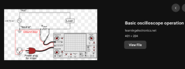
"floating the scope" is slang or shorthand for lifting the chassis ground, which can be dangerous if measuring high voltages. the 2-prong adapter isolates the 3-prong mains plug that gets plugged into the wall outlet (120v ac).

the measurement benefit is being able to connect the scope probe ground to +voltage sources if needed without causing a dead short to earth/chassis ground.

Screenshot 2026-02-09 at 23-33-39 2-prong mains adapter at DuckDuckGo.png
an example, these can be found/sourced easily online or local diy/hardware stores

another thought, out of curiosity, is to activate speaker output (no load) and measure ac (volts or mv) on each channel (system on/active). depending on dmm ability might try hz/frequency measurement as well even though a scope gives a better picture of the situation.
 
I actually have one of those adapters. So, looking for any ACV on the pins of IC101? Any reason why I couldn't just use my Fluke meter on ACV or ACmV- or is that not safe or effective?
 
Last edited:
Any reason why I couldn't just use my Fluke meter on ACV or ACmV- or is that not safe or effective?
you could try, it wont hurt anything, but usually when there is a dc voltage in a circuit it confuses a dmm when trying to look for an ac component (ac rides dc level hence the existence of dc offset). sort of like measuring resistance when there is a voltage across a component, doesnt work out so well.

the ac you are hunting for is the hum or noise that isnt part of the usual dc level for the circuit. a scope make things easier to see and can switch between ac and dc coupling.
 
you could try, it wont hurt anything, but usually when there is a dc voltage in a circuit it confuses a dmm when trying to look for an ac component (ac rides dc level hence the existence of dc offset). sort of like measuring resistance when there is a voltage across a component, doesnt work out so well.

the ac you are hunting for is the hum or noise that isnt part of the usual dc level for the circuit. a scope make things easier to see and can switch between ac and dc coupling.
That makes perfect sense- did not think of that. I'll get in there and see what I see.
 
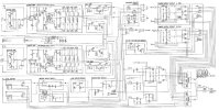
Bad news. Before I went to the scope I checked DCV and ACV across the speaker terminals with the Fluke VOM. On the R-Ch, 4.6mV DC (which is about normal when the thing was working fine) and 3mV AC. On the troublesome L-Ch, 6.5mV DC and 22mV AC. Also checked voltage on pins 1-7 on IC101 since I hadn't done that yet. Pin 1: L=2.3 / R=2.6; Pin 2: L=1.7 / R 1.8; Pin 3: L=.56 / R .7; Pin 4: L= -.06 / R=0; Pin 5: L= -.9 / R= -.7; Pin 6: L= -1.9 / R= -1.8; Pin 7: L= -2.2 / R= -2.5 (All DCV). Didn't get anything definitive out of the scope reading on pins 8-14 on the chip, but I'm also far from an expert with a scope. Then went to checking to see what I might see on the speaker terminals and about that time both fuse FU3 and 4 on the right there blew. No idea why. I'd been tinkering with the unit for a bit and that L-Ch sink heats up quick so wondering if something gave out or if I hit something with my probe or probe ground wire I shouldn't have. Adding in the block diagram in case it helps- hope you can read that. After I get some replacement fuses I'm wondering if I should replace to see what happens, or is it better to pull it apart and start checking for bad components?

1770852407686.jpeg
1770913362705.png
 

Attachments

  • Overload.JPG
    Overload.JPG
    108 KB · Views: 2
  • Amp Block.jpg
    Amp Block.jpg
    117.9 KB · Views: 2
Last edited:
pins 1 and 7 seem to be healthy, schematic indicates 8 and 14 should be around -3.3/3.3 respectively.

are you using a dim bulb tester or monitoring the mains consumption?

Screenshot 2026-02-12 at 12-27-29 ZHURUI PR10-E US15A Power Meter Plug_Home Power metering Soc...png
an example of a mains kilowatt meter on amzn, i use this particular brand/model plus a variac.

some noteworthy imbalances with the chip dc voltages L vs R channel. R: pins 2 vs 6 and 3 vs 5 seem balanced, not so much for L-ch. the balancing act between positive vs negative.

looks like fuse 3 and 4 are 800ma timed/slow blow that feed a +/- 20v circuit.
 
pins 1 and 7 seem to be healthy, schematic indicates 8 and 14 should be around -3.3/3.3 respectively.

are you using a dim bulb tester or monitoring the mains consumption?

View attachment 3697883
an example of a mains kilowatt meter on amzn, i use this particular brand/model plus a variac.

some noteworthy imbalances with the chip dc voltages L vs R channel. R: pins 2 vs 6 and 3 vs 5 seem balanced, not so much for L-ch. the balancing act between positive vs negative.

looks like fuse 3 and 4 are 800ma timed/slow blow that feed a +/- 20v circuit.
I have my standard homemade Dim bulb tester with just the light bulb- nothing fancy. Pins 8 and 14 were correct. Assuming there's no major damage done, I'm thinking of replacing all the fusible resistors in the Amp C section and the 10 and 100 ohm fusible resistors in the Amp A section. Want to go back and pull them all and check them, but thinking if I'm pulling, why not replace. I ordered all metal film 1%. What do you think- worth it or a waste of time?
 
I ordered all metal film 1%. What do you think- worth it or a waste of time?
reducing the amount of uncertainty/variables is usually a good thing aka when in doubt change it out, it most likely needs it anyway.

seems like there are the 4.7 and 47 resistances as well. unfortunately the chip will always be a suspect of last resort since it can be a mystery box of unknown lifespan. integrated circuits (ic chips) and transistors have a chaotic lifespan in the field regardless of thermal environment, diodes are in the same boat to some extent especially zener's over a particular value.

there might be one or more small signal transistors causing issues or it could a chip or... both. welcome to the wonderful world of "what if" troubleshooting "vintage edition". typically there is a thread or dozen about a particular piece of electronics, joys of searching forum post entries. top ten bad transistor list can be a fun read (@dlucy / @Blue Shadow / @Hyperion and many others).

either way the learning process takes time (learning curve with anything new) plus developing a diagnostic procedure that makes sense to the individual with a classroom size of one. the joys of a hobby perhaps.

 
Back
Top Bottom