• The move to the new server is done. There are some software and database maintenance updates in process. This has us passing the hat around to help out. We appreciate any donations. Seriously, even a dollar helps. The payment page may be found here - https://www.audiokarma.org/support.html

Pioneer M-90 Issue- need help.

reducing the amount of uncertainty/variables is usually a good thing aka when in doubt change it out, it most likely needs it anyway.

seems like there are the 4.7 and 47 resistances as well. unfortunately the chip will always be a suspect of last resort since it can be a mystery box of unknown lifespan. integrated circuits (ic chips) and transistors have a chaotic lifespan in the field regardless of thermal environment, diodes are in the same boat to some extent especially zener's over a particular value.

there might be one or more small signal transistors causing issues or it could a chip or... both. welcome to the wonderful world of "what if" troubleshooting "vintage edition". typically there is a thread or dozen about a particular piece of electronics, joys of searching forum post entries. top ten bad transistor list can be a fun read (@dlucy / @Blue Shadow / @Hyperion and many others).

either way the learning process takes time (learning curve with anything new) plus developing a diagnostic procedure that makes sense to the individual with a classroom size of one. the joys of a hobby perhaps.

Thanks- and stay tuned
 
reducing the amount of uncertainty/variables is usually a good thing aka when in doubt change it out, it most likely needs it anyway.

seems like there are the 4.7 and 47 resistances as well. unfortunately the chip will always be a suspect of last resort since it can be a mystery box of unknown lifespan. integrated circuits (ic chips) and transistors have a chaotic lifespan in the field regardless of thermal environment, diodes are in the same boat to some extent especially zener's over a particular value.

there might be one or more small signal transistors causing issues or it could a chip or... both. welcome to the wonderful world of "what if" troubleshooting "vintage edition". typically there is a thread or dozen about a particular piece of electronics, joys of searching forum post entries. top ten bad transistor list can be a fun read (@dlucy / @Blue Shadow / @Hyperion and many others).

either way the learning process takes time (learning curve with anything new) plus developing a diagnostic procedure that makes sense to the individual with a classroom size of one. the joys of a hobby perhaps.

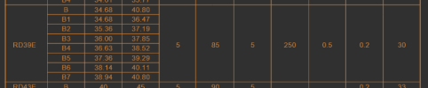
Do you by chance have recommended replacements for the zeners? RD39EB, RD13EB and RD12EB? Best I can figure is a 3.9V 1W; 13V 1/2W and 12V 1/2W. Does that sound right?
 
Last edited:
rd39e (b level of tolerance) would be 39v 0.5w judging by the zener spec sheet.

Screenshot 2026-02-16 at 10-08-59 RD200E NEC Alldatasheet - RD200E.PDF.png

bumping them all up to 1w wouldnt be a bad idea, something i usually do. should be some common drop-in replacements on the usual parts sites (digikey, mouser, others...).
 

Attachments

rd39e (b level of tolerance) would be 39v 0.5w judging by the zener spec sheet.

View attachment 3701151

bumping them all up to 1w wouldnt be a bad idea, something i usually do. should be some common drop-in replacements on the usual parts sites (digikey, mouser, others...).
THANK YOU!
 
Does this look like the correct reading for an SB750A and SD836A? Transistors Q136 and Q137 in the power supply circuit on the left channel board. Schematic doesn't show the diode between emitter and collector, but they test that way.
 

Attachments

  • SB750A.jpg
    SB750A.jpg
    116 KB · Views: 0
  • SD836A.jpg
    SD836A.jpg
    110.1 KB · Views: 0
looks like 2sb750a (pnp) is a darlington, has multiple internal components.

Screenshot 2026-02-18 at 22-13-18 2SB750 ETC Alldatasheet - 2SB750.PDF.png
from the datasheet

and the 2sd836a (npn) would be the complementary flavor for a +supply circuit vs pnp for -supply circuit design.
 

Attachments

looks like 2sb750a (pnp) is a darlington, has multiple internal components.

View attachment 3703102
from the datasheet

and the 2sd836a (npn) would be the complementary flavor for a +supply circuit vs pnp for -supply circuit design.
Thanks for the clarification. Left channel- I've replaced a few resistors and zeners on the amp A PCB. Rechecked a few transistors and some caps as well. With the exception of the .47ohm ceramics, I replaced all the resistors on the amp C PCB. Checked all the power transistors on that PCB as well- no issues. Nothing I pulled and/or replace looked bad on the meter or tester, which I'll admit was disappointing. Going to replace the fuses and fire it up tonight, starting with the DB-tester, and see what happens. Hoping the blown fuses were the result of hitting something I shouldn't have with the scope probe.
 
hopefully no need for a fire extinguisher within arms reach. i really should invest in such a device one of these days...
 
hopefully no need for a fire extinguisher within arms reach. i really should invest in such a device one of these days...
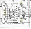
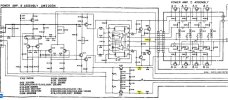
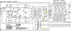
Got sidetracked so just getting back to it. Kind of avoiding it too since not messing with it means I still haven't blown it up : ) Anyway, after all that replacing of parts, no smoke, fire or blown fuses, but no improvement either. Still with the L-Ch, on the IC: pin 8 -3.3V; pin 14 3.2V; pin 10 -84.5mV; pin 11 6mV; pin 12 98.5mV. Don't know that this is an issue but also checked the mica? caps around that IC. C121 88pf; C123 91pf; C115 56pf; C117 57pf; C119 138 pf. All low according to what's posted on the attached schematic. Thoughts- am I looking at a bad chip?

1771710623542.jpeg
 
ac voltage measurements (dmm or scope) at pins 8 & 14 with nothing connected vs shorted audio input connections (min/max volume into dummy load)? dim bulb helps to protect from a runaway condition happening plus the bulb is quick indication of the amp loading down from increased signal, noise in this case.

compare ac voltage measurements between pins 14/13 and 8/9 (input vs output). sad that it took me this long to think about something simple.

on a different note: trying to figure out if a noise/hum exists upstream or downstream from the volume pot or if the volume control is introducing noise into the system before we increase focus on the chip swap/replacement.

maybe install chip sockets for a diagnostic channel swap to hear if the hum and bias also follow. although before that surgery happens perhaps spray the volume pot/control if by chance there is an intermittent wiper/crud issue. any tone controls and selector switches would be suspect as well.

their seems to be a few relays in the front end circuit, an oddball maneuver might help which involves tapping the relay housing with a non-conductive object (handle of a screwdriver or something) and listen for any change in idle noise floor (speakers connected). the joys of non-standard diagnostic procedures.
 
ac voltage measurements (dmm or scope) at pins 8 & 14 with nothing connected vs shorted audio input connections (min/max volume into dummy load)? dim bulb helps to protect from a runaway condition happening plus the bulb is quick indication of the amp loading down from increased signal, noise in this case.

compare ac voltage measurements between pins 14/13 and 8/9 (input vs output). sad that it took me this long to think about something simple.

on a different note: trying to figure out if a noise/hum exists upstream or downstream from the volume pot or if the volume control is introducing noise into the system before we increase focus on the chip swap/replacement.

maybe install chip sockets for a diagnostic channel swap to hear if the hum and bias also follow. although before that surgery happens perhaps spray the volume pot/control if by chance there is an intermittent wiper/crud issue. any tone controls and selector switches would be suspect as well.

their seems to be a few relays in the front end circuit, an oddball maneuver might help which involves tapping the relay housing with a non-conductive object (handle of a screwdriver or something) and listen for any change in idle noise floor (speakers connected). the joys of non-standard diagnostic procedures.
So much appreciate your suggestions- this thing is really pissing me off though! Just using my Fluke 117 VOM: IC pins 8 and 9: .05VAC; pins 13 and 14 fluctuate between .02VAC and 0V. That's with the unit turned on, no signal and vol at 0. Decided to flip it over and check the right channel IC. DC voltage: pin 8: -3.2V; pins 10, 11,12, 14 all 0V- that was not the case before the fuses blew. Prior, the DCV on the emitters of the R-Ch power transistors were in the 34mV to 48 mV (+/-) range. Current R-Ch ACV: pins 8,9,13,14 all .7VAC. Thinking back, when those fuses blew, I was checking to see if there was AC voltage on the speaker terminals and I believe I had my scope probe ground lead to the R-Ch (-) speaker terminal and probe to R-Ch (+) speaker terminal. Would that have caused the thing to blow fuses?
 
Last edited:
this thing is really pissing me off though!
this might sound strange, anger is part of the diagnostic process. have yet to meet an auto mechanic with 10/20/30 years under their belt who has not verbally abused the four wheel monster on the repair lift.

scope probe ground lead to the R-Ch (-) speaker terminal and probe to R-Ch (+) speaker terminal. Would that have caused the thing to blow fuses?
with a common ground amp, having scope ground on negative output terminal shouldnt be an issue. although its ideal to float the scope with the 2-prong adapter mentioned earlier just in case. scope probe is around 1meg or a high resistance so causing a low resistance event between probe and scope ground is highly unlikely.

the fuses look like they feed a +/- 20v rail system which then gets adjusted by various downstream transistors for +/- 12v, +9v, +6v, -5.6v and maybe a few other variations. how do the fuse(s) look physically? did the fuse element get blown up / residue plastered on the inside of the glass tube or was it a non-violent/gradual melting until the element went open?

being a slow/timed fuse they can handle beyond their rating for a few cycles before the element eventually melts open. it gives an ideal as to how much current was requested through the fuse i.e. dead short vs gradual/aged usage.

if pins 14/1 have no dc that is definitely a problem. should do some resistance measurements on the chip (power off unplugged system) to see if there is an internal meltdown (+v now shorted to another pin) or if whatever feeds the +3.3v was damaged/aged out of spec.

the game is afoot, not that it wasnt already there. a system full of vintage parts is also full of variables in every direction.
 
this might sound strange, anger is part of the diagnostic process. have yet to meet an auto mechanic with 10/20/30 years under their belt who has not verbally abused the four wheel monster on the repair lift.


with a common ground amp, having scope ground on negative output terminal shouldnt be an issue. although its ideal to float the scope with the 2-prong adapter mentioned earlier just in case. scope probe is around 1meg or a high resistance so causing a low resistance event between probe and scope ground is highly unlikely.

the fuses look like they feed a +/- 20v rail system which then gets adjusted by various downstream transistors for +/- 12v, +9v, +6v, -5.6v and maybe a few other variations. how do the fuse(s) look physically? did the fuse element get blown up / residue plastered on the inside of the glass tube or was it a non-violent/gradual melting until the element went open?

being a slow/timed fuse they can handle beyond their rating for a few cycles before the element eventually melts open. it gives an ideal as to how much current was requested through the fuse i.e. dead short vs gradual/aged usage.

if pins 14/1 have no dc that is definitely a problem. should do some resistance measurements on the chip (power off unplugged system) to see if there is an internal meltdown (+v now shorted to another pin) or if whatever feeds the +3.3v was damaged/aged out of spec.

the game is afoot, not that it wasnt already there. a system full of vintage parts is also full of variables in every direction.
Here's what the fuses look like. I've pulled the right channel out and am replacing the same resistors and diodes I did on the left. Don't expect that to fix anything, but at least it will get that out of the way. However, on the Amp B PCB I found the (2) 10 ohm fusible resistors a bit out. R174 at 12 ohms and R176 at 17.4 ohms. R162 should be 100 but was at 160 ohms. No bad diodes on that card. On to the Amp D card. Will probably check some components that feed the 3.3V to pin 14 since that was at zero. Otherwise, it's fire it back up and check voltages, but I'm extremely nervous about that since bias is so high on the left channel and it gets to cookin. If I put the thing on the DB tester it drops the 67VDC (+/-) rail voltage down to about 36V. Can't really troubleshoot voltages with that- can I?

1771888258642.jpeg
 

Attachments

  • Fuse.jpg
    Fuse.jpg
    31 KB · Views: 5
  • RC Amp.JPG
    RC Amp.JPG
    89.6 KB · Views: 5
Here's what the fuses look like.
looks like fuse element is still intact so perhaps a weak spot blowout

extremely nervous about that since bias is so high on the left channel and it gets to cookin. If I put the thing on the DB tester it drops the 67VDC (+/-) rail voltage down to about 36V. Can't really troubleshoot voltages with that- can I?
part of the beauty when using a dim bulb is being able to starve the system from doing more damage to itself aka safety net. depending on dim bulb wattage being used it is easy enough to measure dc rails at the filter caps and using the new/lower number as a point of reference (scaling high numbers downward).

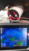
the +/- amp rails might not be anywhere near schematic spec but there is a voltage on the circuit to give an idea of what has current flow vs what does not vs component internally low/no resistance and heating up (stealing the show). which is where a thermal camera can help for quick identification.

using a variac plus a dim bulb can be a best of both worlds diagnostic safety net, dialing down mains voltage from 120v to 60v or 80v therefore reducing destructive potential (lower idle wattage) and the dim bulb is a current limiter (ultimate safety net when used properly).

works great with tube gear, when dealing with b+ between 350vdc-1200vdc (hello 845 big bottle). contemplating an 813 based mono block design with variable b+ throttle from 300vdc to around 2200vdc but now i am getting way off topic, oops.

some systems that have safety/protection circuits with or without relays might have a power up issue, pioneer spec-4 amp comes to mind recently, great way of cleaning relay contacts by simulating 1 year of on/off cycles in about 3-5 seconds. other systems refuse to do low power up since the circuits might perceive it as a brown-out threshold i.e. mains below 85v or 90v detected as insufficient for power up.

using 40w or 80w dim bulb can be sufficient to safely troubleshoot especially if a probe slips and dead shorts a transistor or something that could cause a chain reaction e.g. 21 component salute (releasing lots of magic smoke at once, very bad). some gear tends to need a 100w or 200w dim bulb due to inrush and high idle wattage, the realm of class-a and high output systems (phase linear is a monster example).
 
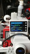
*somewhat example of what i am using on the bench, not the best camera angle

*apparently i have a quick example of holding back a runaway condition

somewhere in my "menagerie" picture book mess there is an update as to variac-bulb-n-stein "current version" since it is a constantly evolving design depending on testing needs/comfort and scrap within reach.
 
looks like fuse element is still intact so perhaps a weak spot blowout


part of the beauty when using a dim bulb is being able to starve the system from doing more damage to itself aka safety net. depending on dim bulb wattage being used it is easy enough to measure dc rails at the filter caps and using the new/lower number as a point of reference (scaling high numbers downward).

the +/- amp rails might not be anywhere near schematic spec but there is a voltage on the circuit to give an idea of what has current flow vs what does not vs component internally low/no resistance and heating up (stealing the show). which is where a thermal camera can help for quick identification.

using a variac plus a dim bulb can be a best of both worlds diagnostic safety net, dialing down mains voltage from 120v to 60v or 80v therefore reducing destructive potential (lower idle wattage) and the dim bulb is a current limiter (ultimate safety net when used properly).

works great with tube gear, when dealing with b+ between 350vdc-1200vdc (hello 845 big bottle). contemplating an 813 based mono block design with variable b+ throttle from 300vdc to around 2200vdc but now i am getting way off topic, oops.

some systems that have safety/protection circuits with or without relays might have a power up issue, pioneer spec-4 amp comes to mind recently, great way of cleaning relay contacts by simulating 1 year of on/off cycles in about 3-5 seconds. other systems refuse to do low power up since the circuits might perceive it as a brown-out threshold i.e. mains below 85v or 90v detected as insufficient for power up.

using 40w or 80w dim bulb can be sufficient to safely troubleshoot especially if a probe slips and dead shorts a transistor or something that could cause a chain reaction e.g. 21 component salute (releasing lots of magic smoke at once, very bad). some gear tends to need a 100w or 200w dim bulb due to inrush and high idle wattage, the realm of class-a and high output systems (phase linear is a monster example).
Still working on replacing and checking components on the right channel. I bought this thing used years ago, used it off and on and never had a problem, but also never checked it out other than the DC offset at about 4mv. Never put it on a DB tester either until after i recapped it. Once i completed the recap I first turned it on with the DB and it was a little brighter than other amps I've worked on, but also read this thing has a high current draw. So, took it off the DB and it worked fine for a while until i noticed the hum. With that I started looking at it internally and noted the high heat on the left channel due the high bias voltage out of the PA0016 chip. Don't know if that's new, or if it had been that way for a while since, besides the hum, the thing still produced audio just fine. Noting now that the right channel bias is also higher than it should be, is it more likely the chips are bad? My DB tester currently has a 200 watt bulb in it and it appears to be a bit brighter now than it was after the recap as I recall. Anyway, should I use a lower watt bulb to recheck the voltages after I put this back together?
 
also read this thing has a high current draw. So, took it off the DB and it worked fine for a while until i noticed the hum.
high wattage solid state amps can idle around 100w depending on how far into class-a design the circuit engineer was trying to achieve. the 200w bulb helps to feed the natural hunger but it also allows for more stress/damage to occur if a few things are out of spec, like bias circuit/components/chips. the bulb is still a good safety net to some degree but using too high of a wattage defeats the purpose.

taking the amp off the chain (dim bulb) and the hum starts, points to some aged/stressed parts that need replacing not to mention inspecting boards for broken solder joints (hot-cold cycles take their toll).

With that I started looking at it internally and noted the high heat on the left channel due the high bias voltage out of the PA0016 chip. Don't know if that's new, or if it had been that way for a while since, besides the hum, the thing still produced audio just fine.
its starting to look more like the bias servo chip is drifting and that would be an easy way to disrupt a channel or two in terms of loading down the system regardless of signal input/output load connected (motor idling about 1400 rpm type of thing vs 1000 or lower factory spec).

another analogy would be car tires that are new vs half worn vs bald. can still drive on balds tires but they can blow out at any time. warning signs like tires not keeping pressure for more than a week or month can be ignored only for so long until the next weakest link is compromised.

My DB tester currently has a 200 watt bulb in it and it appears to be a bit brighter now than it was after the recap as I recall. Anyway, should I use a lower watt bulb to recheck the voltages after I put this back together?
after a recap a system can pull more wattage vs the older "out of spec" components. especially if crucial power supply related components are involved. some of the high measuring fusible resistors might adjust the idle as well. the closer to nominal/factory spec the amp gets will give a better picture as to what the normal idle should be.

either way this project will be a useful learning experience and help create a diagnostic methodology that can be used on future gear/distractions. the m-90 definitely needs an update/overhaul regardless.

sourcing a pair of new-old-stock chips might be challenging (too many fakes on the market/ebay/wherever for somethings) or some hifi nut has a few hundred of them hiding in their electronics collection involving half a dozen commercial sized storage units.

using lower wattage bulbs are useful for lower wattage gear even though some high powered amps might be tolerant of going on a temporary energy diet. not exactly a one size fits all bulb solution but experience can fill in some gaps as to what wattage should be used when. everybody has a slightly different definition of diagnostic safety when working on audio gear (too safe/slow can create false positives, been there done that). case in point, discharging power caps with a wrench or screwdriver vs lamp with series resistor or just a resistor.
 
high wattage solid state amps can idle around 100w depending on how far into class-a design the circuit engineer was trying to achieve. the 200w bulb helps to feed the natural hunger but it also allows for more stress/damage to occur if a few things are out of spec, like bias circuit/components/chips. the bulb is still a good safety net to some degree but using too high of a wattage defeats the purpose.

taking the amp off the chain (dim bulb) and the hum starts, points to some aged/stressed parts that need replacing not to mention inspecting boards for broken solder joints (hot-cold cycles take their toll).


its starting to look more like the bias servo chip is drifting and that would be an easy way to disrupt a channel or two in terms of loading down the system regardless of signal input/output load connected (motor idling about 1400 rpm type of thing vs 1000 or lower factory spec).

another analogy would be car tires that are new vs half worn vs bald. can still drive on balds tires but they can blow out at any time. warning signs like tires not keeping pressure for more than a week or month can be ignored only for so long until the next weakest link is compromised.


after a recap a system can pull more wattage vs the older "out of spec" components. especially if crucial power supply related components are involved. some of the high measuring fusible resistors might adjust the idle as well. the closer to nominal/factory spec the amp gets will give a better picture as to what the normal idle should be.

either way this project will be a useful learning experience and help create a diagnostic methodology that can be used on future gear/distractions. the m-90 definitely needs an update/overhaul regardless.

sourcing a pair of new-old-stock chips might be challenging (too many fakes on the market/ebay/wherever for somethings) or some hifi nut has a few hundred of them hiding in their electronics collection involving half a dozen commercial sized storage units.

using lower wattage bulbs are useful for lower wattage gear even though some high powered amps might be tolerant of going on a temporary energy diet. not exactly a one size fits all bulb solution but experience can fill in some gaps as to what wattage should be used when. everybody has a slightly different definition of diagnostic safety when working on audio gear (too safe/slow can create false positives, been there done that). case in point, discharging power caps with a wrench or screwdriver vs lamp with series resistor or just a resistor.
Found a site in Europe that specializes in old school original parts- looked legit. Said they had original pioneer chips at $70 a pop. Was going to order, but turned out they only had one so decided against. Hopefully it's something other than that, but I'm getting that feeling : ( Back to work....
 
i would start with 100w or 120w (60+60 depending on availability) and see if the protection circuit has enough power to activate (latch the relay) and be stable. if not, then go up to 200w although constant high brightness is not a good sign. usually there is a bright moment when powering up from a cold start (power caps mostly discharged) after which the bulb starts to dim slowly.

using a kilowatt meter helps to see how hungry the system is, not easy to see otherwise. if the patient has a pulse and how high is the metaphorical heart rate, might be one way of looking at it.
 
Back
Top Bottom