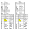
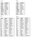
lots of static checks for the chip, no idea if there will be a smoking gun as to leakage or something noticeably out of tolerance.
View attachment 3715319
*a repeat from the previous page, to make things easier.
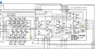
measuring across the current source pins (double circle symbols) would be a good starting point.
between pins:
1/14
7/8
9/13
8/9
13/14
10/11
11/12
1/7
8/14
comparing each chip upper vs lower outputs (each triangle symbol):
between pins:
9 and all its inputs
vs
13 and all its inputs
sometimes there will be an obvious low/high resistance but no guarantees there will be any useful data from this procedure. using an LCR meter at a particular frequency can find an anomaly when doing in-circuit diagnostics of circuit pathways but it helps to have "known good" range to compare the measurements with.
the joys of being a detective and flying blind for most of the case until things click, in a good way.
*operational transconductance amplifier, pioneer chip might be a variation or something





 Still waiting on the chips. Shipped but no tracking. If i get bored waiting I may put the originals back in but flip channels to see if the symptoms move with the chips, but a little hesitant. Don't want to screw anything else up.