• The move to the new server is done. There are some software and database maintenance updates in process. This has us passing the hat around to help out. We appreciate any donations. Seriously, even a dollar helps. The payment page may be found here - https://www.audiokarma.org/support.html

Pioneer sx-1050 no voltage at output caps problem

I went ahead and purchased the transformer that was listed. For now it will be a waiting game. I am going to clean the heat grease off the output transistors and have them ready. Im sure it is best to wait until transformer is installed and secondary voltages are confirmed correct before re-installing output transistors back on heatsink
 
I am going to suggest testing the replacement transformer before installing it to be sure the wiring is figured out and it is functioning correctly.
After the transformer is installed and the power supply voltages are all verified correct it will be time to reinstall the transistors and heatsink.
 
I am going to suggest testing the replacement transformer before installing it to be sure the wiring is figured out and it is functioning correctly.
After the transformer is installed and the power supply voltages are all verified correct it will be time to reinstall the transistors and heatsink.
Sounds good to me. Thanks again
 
@merlynski Hi, Im glad I purchased that att-290 transformer because I still haven't found a att-266 exact replacement. I been trying to figure out how I am going to test the replacement transformer and wire it. I do have a variac that I can use. I also purchased a rectifier from mouser although not sure If I should replace it at this time. Any thoughts?
 
I don't think you need a variac. I would use a dim bulb tester or, or at least a fuse on first power up.
The first testing I would do is with the meter on ohms range. Verify continuity of each winding end to end, then verify that each individual winding is not shorted to another winding or the case.

On the primary side you should have continuity from (if it matches the SX-1250 transformer colors):
Black to Red and Grey, no continuity to any other wires or case.
White to Yellow and Brown, no continuity to any other wires or case.
On the secondary side (SX-1050 schematic):
White to each Red, no continuity to any other wires or case.
Brown to each Green and each Orange, no continuity to any other wires or case.
Blue wires to each other, no continuity to any other wires or case.

BENCH TEST, before installation . . .
To set up the transformer for 120v (USA) I would connect the primary side wiring like this:
Black to White, then to one side of the AC line (DBT).
Brown to Grey, then to the other side of the AC line (DBT).
This makes the primary side windings connected in parallel, for the 120vAC input
Cap off (no connection) the Yellow or Red wires.
Make sure none of the secondary side wires are shorting to any other wires or metal objects.
Power up. I do not expect the DBT bulb to light up, as there is no load, except a tiny bit of magnetizing current in the primary side. If you have a bright bulb you have a problem.
Verify ≈120vAC across the primary winding side. Careful, this is full line voltage upload_2021-12-7_14-12-50.gif !!
Next step is to measure secondary side AC voltages:
Blue to Blue, about 9vAC.
White to each Red, about 60vAC upload_2021-12-7_14-20-16.gif
Brown to each Green, about 23vAC.
Brown to each Orange, about 70vAC.upload_2021-12-7_14-20-20.gif
These are not critical measurements, as a unloaded secondary winding may read high.
 
Last edited:
I don't think you need a variac. I would use a dim bulb tester or, or at least a fuse on first power up.
The first testing I would do is with the meter on ohms range. Verify continuity of each winding end to end, then verify that each individual winding is not shorted to another winding or the case.

On the primary side you should have continuity from (if it matches the SX-1250 transformer colors):
Black to Red and Grey, no continuity to any other wires or case.
White to Yellow and Brown, no continuity to any other wires or case.
On the secondary side (SX-1050 schematic):
White to each Red, no continuity to any other wires or case.
Brown to each Green and each Orange, no continuity to any other wires or case.
Blue wires to each other, no continuity to any other wires or case.

BENCH TEST, before installation . . .
To set up the transformer for 120v (USA) I would connect the primary side wiring like this:
Black to White, then to one side of the AC line (DBT).
Brown to Grey, then to the other side of the AC line (DBT).
This makes the primary side windings connected in parallel, for the 120vAC input
Cap off (no connection) the Yellow or Red wires.
Make sure none of the secondary side wires are shorting to any other wires or metal objects.
Power up. I do not expect the DBT bulb to light up, as there is no load, except a tiny bit of magnetizing current in the primary side. If you have a bright bulb you have a problem.
Verify ≈120vAC across the primary winding side. Careful, this is full line voltage View attachment 2415293 !!
Next step is to measure secondary side AC voltages:
Blue to Blue, about 9vAC.
White to each Red, about 60vAC View attachment 2415304
Brown to each Green, about 23vAC.
Brown to each Orange, about 70vAC.View attachment 2415305
These are not critical measurements, as a unloaded secondary winding may read high.

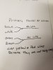
Oh man Im very grateful for this information. If I understand correctly for primary parallel wiring I am to connect Black & White together and connect them to one side of AC line and connect Grey & Brown together and connect to other AC line like in my drawing 20211207_201936.jpg
 
I lost track on this thread and was surprised to read that it is a transformer issue, the worst it could be but so be it and you managed to find another one, which is exactly like the one I bought of the bay a short while ago.
So I needed to test it out and your thread inspired me to test mine out today, post the results for you, confirm your wiring as above.
I tested mine on the bench with a DBT, which of coarse did not even blink.
You can also measure to the center taps, which I did, to verify that they have continuity and produce the 1/2 of the total.
Really makes you wonder why they fail, I have had only one fail on me, in a Sansui G-7500, which consistently blew output devices because it was too much supply for the lack of output stage devices.
Good Luck and happy holidays Rick
 

Attachments

  • ATT-290-Measured.JPG
    ATT-290-Measured.JPG
    91.3 KB · Views: 21
Last edited:
You got it. That should maintain the correct phasing in the primary side.

I lost track on this thread and was surprised to hear that it is a transformer issue, the worst it could be but so be it and you managed to find another one, which is exactly like the one I bought of the bay a short while ago.
So I needed to test it out and your thread inspired me to test mine out today, post the results for you, confirm your wiring as above.
I test my on the bench with a DBT, which of coarse did not even blink.
Really makes you wonder why they fail, I have had only one fail on me, one in a Sansui G-7500, which consistently blew output devices because it was too much supply for the lack of output stage devices
Good Luck and happy holidays Rick
Thanks for the update and test results. Nice to see the actual voltages, instead of my guesstimates :D!
 
This is the first I have seen a secondary winding fail. Usually it is the thermal fuse on the primary side (if there is one) that opens from the transformer overheating. I would love to dissect this failed unit to see what went wrong.
 
Yes it is usually the primary that fails open. Getting into them ain't no fun, lots of stinky? varnish to deal with, reminds me of working in the electric motor re-winding shop :)
 
I lost track on this thread and was surprised to read that it is a transformer issue, the worst it could be but so be it and you managed to find another one, which is exactly like the one I bought of the bay a short while ago.
So I needed to test it out and your thread inspired me to test mine out today, post the results for you, confirm your wiring as above.
I tested mine on the bench with a DBT, which of coarse did not even blink.
You can also measure to the center taps, which I did, to verify that they have continuity and produce the 1/2 of the total.
Really makes you wonder why they fail, I have had only one fail on me, in a Sansui G-7500, which consistently blew output devices because it was too much supply for the lack of output stage devices.
Good Luck and happy holidays Rick
Very nice, Thank you. Just like @merlynski said to wire it. I appreciate you guys time and knowledge. I should be receiving the transformer bi this Friday. Happy Holidays to you too. Thanks again
 
This is the first I have seen a secondary winding fail. Usually it is the thermal fuse on the primary side (if there is one) that opens from the transformer overheating. I would love to dissect this failed unit to see what went wrong.
I may be able to arrange that. Leave it to me to have bought a Lemon... Atleast I was able to deal with the seller and get half my $ back. Thank you guys for everything. You guys have been very helpful. I will update when I receive the transformer and start testing transformer out of circuit
 
You got it. That should maintain the correct phasing in the primary side.


Thanks for the update and test results. Nice to see the actual voltages, instead of my guesstimates :D!
You were spot on about the primary wiring . Guesstimates are better than nothing to someone like me
 
I got some help from Watthour, who provided me a schematic for the SX-1250 transformer that had the same multi-voltage wiring configuration and colors, and told me it was a 'standard' Pioneer color scheme for that time.
 
I lost track on this thread and was surprised to read that it is a transformer issue, the worst it could be but so be it and you managed to find another one, which is exactly like the one I bought of the bay a short while ago.
So I needed to test it out and your thread inspired me to test mine out today, post the results for you, confirm your wiring as above.
I tested mine on the bench with a DBT, which of coarse did not even blink.
You can also measure to the center taps, which I did, to verify that they have continuity and produce the 1/2 of the total.
Really makes you wonder why they fail, I have had only one fail on me, in a Sansui G-7500, which consistently blew output devices because it was too much supply for the lack of output stage devices.
Good Luck and happy holidays Rick
Thank you will
I got some help from Watthour, who provided me a schematic for the SX-1250 transformer that had the same multi-voltage wiring configuration and colors, and told me it was a 'standard' Pioneer color scheme for that time.
Nice, thanks for doing research and also thanks to Watthour, thanks to everyone contributing
 
Im still awaiting delivery of the replacement transformer. I will let you guys know when I receive it and how my testing goes
 
No problem here, will keep watching for you . . . :thumbsup:
The transformer just got delivered a lil bit ago. I tested it as you instructed. Tested primary and secondary for continuity. All tested good as in your instructions . I am off for the next 3 weeks so I will start the transformer replacement tomorrow and wire as you instructed and test with DBT. What watt bulb should I use for initial testing? I also have a question about setting dc offset. My question is do I select speaker A, B, C or No speaker selection when setting DC offset? That is not covered in SM or maybe I missed it. I know Im not there yet but wanted to ask you before I forget to ask you again.
 
I use a 100W incandescent in the DBT, it is only used for a very short period of time to watch that it does not stay bright for very long ~ 1-2 seconds and then dims a bit. It is dependant on the load
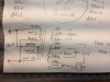
Look at my transformer diagram again, the primary has two coils, that have to be used, in the case of 120V the coils are in parallel. The secondary has three coils, two of them have a center tap.
If you are going to measure DC offset at the speaker terminals, then yes the speaker switch must be enabled. You are supposed to measure DC offset and bias on the amp pcb anyways.
 
Back
Top Bottom