petehall347
the brandy coffee man
if the speaker relay clicks in its ok to hook up to the speaker terminals to set dc offset .



Im going back in to check to see what I did and re-check continuity on primary side again.¿¿ Your primary side continuity test in post #79 does not match the description in post #65 ???
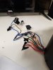
On the primary side you should have continuity from:
Black to Red and Grey, no continuity to any other wires or case.
White to Yellow and Brown, no continuity to any other wires or case.
The winding phase connections have to be correct also, if you hook them up in reverse they oppose each other and you will have little or no output on the secondary side!
Your drawing in post #66 is correct.
You got it. Also remember that the heatsink with the output transistors is still removed from the chassis. I will wait for your instructions on when to re-install the heatsink and plug in the connectors to the output transistors. Im sure that will be after the transformer has been installed and voltage measurements are confirmed good. So tomorrow I will connect the primary wires to receiver and make sure secondary wires do not short on anything then test voltages on secondary wires while using DBT. I will give you update on secondary voltages tomorrow and will wait to hear from you before I proceed to solder secondary wires to pc board. Anything I should do differently or proceed as I wrote above?Thanks! I don't want anybody to get hurt trying to follow my instructions, or damage their Vintage gear. This is a bit of a customization/refurb/repair, got to be extra careful with those.
I understand, I will power up on DBT if all good then go to full mains and test secondary voltages. Earlier I wrote test secondary voltages with DBT so I am correcting that.If you connect the primary side to the SX-1050, the Surge Killer resistor will be in series with the primary, (cause the relay cannot pull in) and may affect the secondary voltages. I would just connect the primary side to the DBT directly for the first powered test. If it passes the DBT (you may not see any flash at all) you can connect the primary side to full mains voltage and measure the secondary voltages. Once that is done I would install the transformer and, leaving the heatsink and transistors un-plugged, try it on the DBT again. Then verify all power supply voltages.
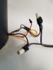
Sure, a temporary connection like a wire nut, or twist and tape, as long as you feel it is safe. The DBT is 'just in case'.@merlynski I am following what u said. First power up DBT if all good go to full mains voltage then get secondary voltage readings. Now can I use a power cord to connect primary wires to DBT?
Ok great. I will do that tomorrow. I will keep you posted on my findings. Thanks I appreciate everythingSure, a temporary connection like a wire nut, or twist and tape, as long as you feel it is safe. The DBT is 'just in case'.
I definitely am using your diagram for reference, As for DC offset yes checking at pcb is the way to go, I was just wondering about the speaker selectors. ThanksI use a 100W incandescent in the DBT, it is only used for a very short period of time to watch that it does not stay bright for very long ~ 1-2 seconds and then dims a bit. It is dependant on the load
Look at my transformer diagram again, the primary has two coils, that have to be used, in the case of 120V the coils are in parallel. The secondary has three coils, two of them have a center tap.
If you are going to measure DC offset at the speaker terminals, then yes the speaker switch must be enabled. You are supposed to measure DC offset and bias on the amp pcb anyways.
Ok nothing smoked, I did verify I was putting in 117vac to primary wires bi putting test leads inside each wire nut. And just as you said the 100w bulb did not light up at allLooks good, go for it!
Will doExcellent!
Next measure ACV on the secondaries.