• The move to the new server is done. There are some software and database maintenance updates in process. This has us passing the hat around to help out. We appreciate any donations. Seriously, even a dollar helps. The payment page may be found here - https://www.audiokarma.org/support.html

Project: Sansui AU-717 (BKs)

Make sure none of the VD1212 replacements (you did replace them, right?) on the EQ board are shorting out against the one switch shaft. One of them is directly under the shaft in close proximity. That bit me once with the smoking resistor syndrome on the power board. :D

I got lucky and caught that little snag just in time on my 517. But it nailed my Brother with his 717, Lol.
 
I did something here - Fully rebuilt the power supply -

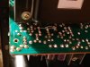
R05, R06, R15, and R16 are getting hot and smoking. Anyone see anything?

Edit -Replaced them with spare 100hm resistors, still get hot and smoke.

R05 smokes whens on DBT within a few seconds. TR01 must be getting too much current... Strange all four resistors get hot... Tough one.

View attachment 1757604 View attachment 1757565 View attachment 1757570 View attachment 1757571 View attachment 1757574 View attachment 1757587

Schematic:

View attachment 1757658 View attachment 1757659
Looking over your BOM I spotted this:

"TR05-TR06 & TR09-10 – 2SC1708 / Now KSA992FB
TR07-TR08 & TR11-12 – 2SA847 / Now KSC1845FB"

If you indeed used a KSA to replace a 2SC and and a KSC in place of a 2SA, then you will indeed have problems. I think you just need to switch these transistors out (preferably with new ones)
 
Looking over your BOM I spotted this:

"TR05-TR06 & TR09-10 – 2SC1708 / Now KSA992FB
TR07-TR08 & TR11-12 – 2SA847 / Now KSC1845FB”
If you indeed used a KSA to replace a 2SC and and a KSC in place of a 2SA, then you will indeed have problems. I think you just need to switch these transistors out (preferably with new ones)

Updated the error. Thanks Gav.
 
Looking over your BOM I spotted this:

"TR05-TR06 & TR09-10 – 2SC1708 / Now KSA992FB
TR07-TR08 & TR11-12 – 2SA847 / Now KSC1845FB"

If you indeed used a KSA to replace a 2SC and and a KSC in place of a 2SA, then you will indeed have problems. I think you just need to switch these transistors out (preferably with new ones)

Woah. Yup, I sure did use the incorrect transistors. Excellent catch - lesson learned for me to read and understand these BOMs before executing. Swapping them out shortly with new ones. Thank you for taking the time to review this.

Make sure none of the VD1212 replacements (you did replace them, right?) on the EQ board are shorting out against the one switch shaft. One of them is directly under the shaft in close proximity. That bit me once with the smoking resistor syndrome on the power board. :D

Haven't gotten that far yet! But I will be sure to take extra precaution when I get there :)

Only have done the tone and now power board. I dunno why but this thing is taking long time to work on. That powerboard took me about 8 hours!
 
Transistors replaced with new proper replacements - Power board is working, no smoking. DBT is happy.

I can't get sound unless i put an audio source into the Pre-amp out (i know). Something still is not 100%.

Flipped the switch to use the power in. An input into the power in produces sound. Any ideas where to start looking regarding the tone board + others?

Thinking of starting to recap the EQ board - Kinda lost here - having a hard time reading the schematic and following the audio path.
 
Last edited:
Fusistors... keep going.

Keepin' going. Do you suspect I blew one during my resistor smoke-o-thon last night? Unit worked flawlessly before I started the power board (tone board already done).

Edit- just checked the four fuse resistors on the EQ board, all within spec according to the MM.

Edit 2 - the aux input seems to skip most of the EQ board and go from the RCA Jack to the input selector pot on the EQ board, skips any semi conductor and goes straight to the tone board.
 
Last edited:
Sorry about the error... you need to verify my lists.

You need to check that power board pins to the EQ board and tone board. You may also want to check the fuses.

Am not talented enough to troubleshoot over the net.

Though a setback... I find I learn much from these and sharpen my schematic reading and electronic skills.

You will get it... just might take some time. You will then start targeting non working units as they can be had for much less coin.

Many times sleeping on it helps.

Best of luck.
 
Transistors replaced with new proper replacements - Power board is working, no smoking. DBT is happy.

I can't get sound unless i put an audio source into the Pre-amp out (i know). Something still is not 100%.

Flipped the switch to use the power in. An input into the power in produces sound. Any ideas where to start looking regarding the tone board + others?

Thinking of starting to recap the EQ board - Kinda lost here - having a hard time reading the schematic and following the audio path.
Pre-Amp out is the output from the preamplifier, not an input. If you didn't clean that switch, it can cause signal problems. It hardly gets used and the tarnish builds up pretty bad on it. Run it back and forth a number of times and try it again in the "connected" position.
 
Good news/bad news.

Good news is I think I know why the tone board is not working... Because it only has a few volts going to it (not 33v like it should).

On the PS board, pins 18, 20, 22, 24 and 26 (red and blue) as well as 17, 19, 21, 23, and 25 (yellow and grey) read only 1 to 2 volts (or negative where it's sopposed to)! These feed the tone board (and EQ). No power = no sound.

Looks like my work on the PS board is not complete. I don't like that both sides are down.

Screenshot_20200209-214100_Drive.jpg


Pre-Amp out is the output from the preamplifier, not an input. If you didn't clean that switch, it can cause signal problems. It hardly gets used and the tarnish builds up pretty bad on it. Run it back and forth a number of times and try it again in the "connected" position.

I plan on cleaning that one up as part of the restore - fortunately I do not believe this is the cause just yet.
 
Good news is I think I know why the tone board is not working... Because it only has a few volts going to it (not 33v like it should).

On the PS board, pins 18, 20, 22, 24 and 26 (red and blue) as well as 17, 19, 21, 23, and 25 (yellow and grey) read only 1 to 2 volts (or negative where it's sopposed to)! These feed the tone board (and EQ). No power = no sound.

Looks like my work on the PS board is not complete. I don't like that both sides are down.
Check the polarity of any/all electrolytics you have replaced carefully - as clearly shown in the schematic clip you posted, your symptoms suggest capacitors installed with incorrect polarity. Also check the semiconductors if your capacitor check does not throw up any mistakes. You'll need to check that you haven't damaged those resistors (R05, R06, R15 & R16). Above all keep the unit ON DBT until the smoking resistor problem has been dealt with. ;)

Focus your attention on the positive regulator first, i.e. TR02 and associated components - the negative regulator (TR04 and associated components) won't work until the positive one is fault free. (same for the other channel) ;)
 
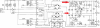
Alrighty - Split the schematic/board down to one side. Furthermore, just the positive voltage side. Heres what I got, voltage just dropping as I go along... Is the answer right in front of me? I think I toasted TRO2? TR06 was just replaced. Thanks for taking a look. Remember, the other side is having the same issue. Although I did not probe it, the 33v at the end is missing.

R08 and R10 seem to ohm at 10k in the circuit, which is their rating.

Capture.PNG

power one side.png

Rough notes, not gospel:

upload_2020-2-10_20-57-32.png

Check the polarity of any/all electrolytics you have replaced carefully - as clearly shown in the schematic clip you posted, your symptoms suggest capacitors installed with incorrect polarity. Also check the semiconductors if your capacitor check does not throw up any mistakes. You'll need to check that you haven't damaged those resistors (R05, R06, R15 & R16). Above all keep the unit ON DBT until the smoking resistor problem has been dealt with. ;)

Focus your attention on the positive regulator first, i.e. TR02 and associated components - the negative regulator (TR04 and associated components) won't work until the positive one is fault free. (same for the other channel) ;)

Thank you, love this advice. Did not know that the negative relies on the positive
 
Last edited:
How did your capacitor polarity checks go?

There seems to be something going on around TR10, ZD02 shouldn't have zero volts across it, suggesting ZD02 is short circuit (or, though unlikely, possibly C18 short circuit), but also TR10 is 'suspect'. You changed TR06, what did you replace it with?

From your voltage readings it appears the resistors R05, R06, R15 & R16 are OK - at least not 'open circuit' - but these do need checking at some point.

You could remove TR10 and TR02 and test them? - re-install if they test OK. (TR02 looks OK - not sure about TR10, test them both anyway). Make SURE you have the correct replacements installed.

So, check ZD02 (zeners do have a habit of going short circuit), and replace if required, try it again after this, if still no-go perform the other checks as above.

Regarding the bit about the positive regulator and the negative regulator depending on it. As you get more experienced you learn to break down bits of circuitry into blocks or 'modules'. In this way you can perform 'divide and conquer' actions, making fault finding less complicated, quicker and thus much easier. ;)
 
Last edited:
How did your capacitor polarity checks go?

There seems to be something going on around TR10, ZD02 shouldn't have zero volts across it, suggesting ZD02 is short circuit (or, though unlikely, possibly C18 short circuit), but also TR10 is 'suspect'. You changed TR06, what did you replace it with?

From your voltage readings it appears the resistors R05, R06, R15 & R16 are OK - at least not 'open circuit' - but these do need checking at some point.

You could remove TR10 and TR02 and test them? - re-install if they test OK. (TR02 looks OK - not sure about TR10, test them both anyway). Make SURE you have the correct replacements installed.

So, check ZD02 (zeners do have a habit of going short circuit), and replace if required, try it again after this, if still no-go perform the other checks as above.

Regarding the bit about the positive regulator and the negative regulator depending on it. As you get more experienced you learn to break down bits of circuitry into blocks or 'modules'. In this way you can perform 'divide and conquer' actions, making fault finding less complicated, quicker and thus much easier. ;)

You' da man!!! I only have one new spare for ZD02 which I slapped in there in the few minutes I have before work. Now seeing 17 +/- volts where there should be 33v. Could be DBT causing that but either way I'll take it! Right channel tone amp is working again! I'll get some more data on what I replaced in a bit with voltages etc. Thank you again!

20200211_080155.jpg
 
Great news, - that 17V you are seeing is probably OK - and only due to the grounding issue, once the board is fully connected up, (and the driver assemblies connected), you should see the full 33V - but now you need to check the negative regulator for that channel (same voltage, but negative = Ok). Then you will need to check the other channel regulators in the same way. ;)
 
Power board is healthy! Getting 33v (32v actually) where I should on both sides. Tone board is now happy, inputs now working. Whew! Wouldn't wish this troubleshooting on anyone. Workbench is a mess.

It was the two zener diodes. I have an interesting story. Dual mono amp, so the power board is split. I only had one new spare zener diode. Put the new spare into one channel and got 17v to the tone board (requires independent 33v from each channel of the powerboard I believe). One channel is still dead because it also has a failed Z diode.

Since I didn't have a spare new zener I used the old one. Well, the side with the old zener probed at 33v where it was previously at 1-2v (looking for 33v).

I probed around the side with the new diode couldn't find any resistors out of spec (giving me 17v instead of 33v). The big positive MJ transistors were giving different values on each side so I assumed why not try and replace them. Coincidentally before that I fat fingered the probe and VERY briefly (famous last words) caused a short on one of the 992 transistors. This killed the new zener diode (remember I'm on the side with the new z diode).

I installed the original zener diode that was once pulled and thrown into the parts bag. Wouldn't you believe it, I had 33v! Both channels now at 33v (32v actually).

I used the incorrect replacement this morning to replace the failed Z diode. 512-1N5234C. Using that dropped the voltage. I have two new spares of the correct one thankfully. Will install them proper. Funny how for once a short actually turned out for the better haha.

Still have the filter caps, EQ and driver boards to do. Big improvement doing just the power and tone board.

IMG_20200211_210600_01.jpg IMG_20200211_205005_01.jpg

Leavening the two Z diodes up top for now. Will clean up soon
 
Last edited:
Nice Job... Winning.

Persistence is the key on these troubleshooting battles.

The amp boards are nice to work on flat on your work space.
 
Last edited:
F-2670 – Pre-Amp Switch Board
C01-C04 – Originally 10uf 25v (polar caps in series for bipolar) / New 2.2 uF 450v Polypropylene Film (Panasonic ECW-FE2W225J)

These polypropylene fit no problem...

GC00dscRO00WC05wkpeNSInWFelul-O5Q-HN8_8wz7TXhfFLxBUhDru6xlRSaN76PZAIMKZlLO8cQqUrALZ73hsIcKb8RqMDkJiyVoQKbe3_hF4vmyoIpHNFpmjn5t1gZrbcj4WoWqJIEWz2aFIh6-VbWDPhRu8Q2t2LwugEU4Yk4R54h9zVZljIDLO1tdQaFkfhqlVIM06quxblfmx2d7yu7eQg3W-jSaVmNZlasS0sVaCM-Ux8QuJ2bV5-Xq0OpgpMMBdwY4-8ErS8XCN0RvtyuevTcQb6tuTuDp8st7CUa5C9V0kPe9KyimZnCpD9ybXa1G0i8hLd9XikTcugEhKwdVrxQ1etHttntqEoea9No_5t8KSKqYJm3iU0qer-82b4bhLjg_mJgyUKEiq9oKLYxoYli9NWOx7Fcn3x4IopbKxvFCpbC5aRne15sNyTpqmdbiGIWJ1MM9ReAx0aHKI3XmnA96DuEH0tATVVTtGhe6jRtw3RWLV9cWIcGa-hlLrw98QoxpY5NWX5pbePlonoQNyfd43v0HQ2u7yxcsbewBCtAOofwbW_ITcVFEsWGkBXyqrBbqe8jcPPR0_zPbJ0NMFkeJlVX2hytH70tseC_TCbiS2CNlKF1bROE6dwKIgrC7crf_SRh7f6VZEZ5CQeP8eAjdJYiFRsbMWqqlmML7hh9rn02w6w_ubni8bWuK0sDj3OP2p2oWgV9iXjoLI4wyYFfUUS72HzPrxpEWmmFsU=w1147-h861-no

pim87_i7aac21WO9RdEZUrthSfjzZI4gcN2IKZMqvPdXdN6cvYGE8MWT7B9LDtb8jkWjFjD4QacEdGwvhAJRA_YSOjIhATkTBVHGTakWnQpK41h71s3q5RwMz4aXUlDqerv0CwXZzXJULN13jY3vXbxrEgvdlvifLyirOytbYfgehqYjXwCih2BWPhW0NVXj_V9lg6iqhKPd1lV2dyWx5iL8LX9W3XBoOl_tzYYDdqh_OZbLy4W-L2s3NVCYpFKvUXY0sZ1wcLVaLhuKrJqVlgXSiQM-ppgT4o9OId1SaMgcMmPQXTPrHoIevxSXoor2BuSWvj0L397Oj09e1oIVc9cqHmKCX-_aGneVA0NlM-tL_ov1DZ8HCa72bD6FmgWODknS-xFCEDVHcU3xO5IchcjLBoL0YTGmLEwRx3BQHWo7QmKKVmAlLrmP5qGr8P8a6uoDm5fcIMMLoru9vlJOm1jwcgvn5X_gGa3ZD9eJPJiJrKLZdTsyvKSsf6kQwvlpTrtsn5SU-FtrznG5v-QcnWSZq642gmABgAzOhmTlaIAt557jVz4I81TqwNYKmHTCr-2jUskG08olrcvg4weyRh5ENjcL7IRC0IF-6uJpFEOE1J_7dWHYAiBBgWgblAIyA_1mKMf4ZpG8y16xkjg-P4fKpPrszdvssDWrbg4YRDq-c4On4mjJ9w=w1147-h861-no

SxGyP2WXL8EDD4VLtC8EZwFJLX6BWe1j1EBvMHpOZ-NNxS4WHp1fwKlH9RlzfgPJmrzn4ayMIoJ7-I8QC8G1QhGUBW_5VUj4smiEL9sfMcNHqZuhPNZRmbO8ppLOG0VQRK1dVLFCS9CChBD82cdA99axaELjJ-bHbFCJfPJELbu_KXqKzMaz3Fvg7MIY7iYE3sgbvHGMj-IXKO43z4MvFPDV0-kczNuQGU-xCs_McLL9EtrF-Tt1e5MtY5BLXyJqD8xDUVe7YUhNSSjIgYMpKkx6etN-Wgl6VxPXoj814hpiSb1ZVMKUHkOcovb-A6-9AWSI2j-3CJ1HiHJrHVTgRS_Azi47dCl7jGTybqzQ8FOWnVKY3qtz067NdLDo6IgASerQuZEQ4P8eGWFxmL6Tb8RE7xgq6V9nRma6zHDcwBMCR71rwrRsWYTxKIMoMPaPvQXiKZzobjzwCQ_4_KYeQtzPJRg0ZuCTJlFtzeJ7NYP7HXKwN-dDkwHDzNa8pOkwtJUIRTLityqFrwtbZI-phf5bbKDHuFcqrc2oybn-7yyxSRVJPbNx-dQKNtjcw1JgVpzit_OS4Zqoe1yzY9X9a3S4vz9jTMMRKfovzUBs6zqmYPZ6hxa28jRDsy31C94j8ZqefMvY_YTSqfa0tNkbmMUuBfsD74eXm_XLgtZFWkhVS2JJsFXsS25cw7gmHD8hbcayw1UPQ9ZEZXR7WjPKdDJ4I5ouwLK73FXXwww74ZQmeIc=w645-h860-no

Couple of questions

Any suggestion for getting the EQ board out to make it easier to work on? Since it's attached via ribbon cables to a cluster of RCA input boards it's pretty much stuck in place. Similar to the preamp switch board, the RCA cluster does not want to come out easily. There is a part of the chassis that blocks me from lifting the EQ board up. I noticed in your photo you had both sides exposed. Did you unsolder the ribbon cable?

For the small preamp switch board, it's held in pretty darn tight by plastic fasteners. I'm assuming just get in there and break them loose? I'm hesitant, there is glue on at least one of them and it looks like it wasn't really meant to be removed. Did you re-glue the fasteners when you put it back in?

Also, getting closer :)

20200213_094402.jpg
 
Any suggestion for getting the EQ board out to make it easier to work on?

You know I did two rebuilds... so you have more pictures to refer too. (however I am few builds down the line).

https://audiokarma.org/forums/index.php?threads/project-sansui-au-717-restore-rebuild.893233/

Unplug everything, pull the shafts forward, and was able to work = didn't recall it being too difficult to get access.

"DID NOT UNSOLDER THE RIBBON CABLES" - Think there might be rear internal cover that is removed.

PPhhtB6B3Jf6KBlxlQSKjH4n1CfGENG_hNx7xy5kLCQnFMV6BuscVEfWwOWypYcCYHEDvZPnzR2qBNX4mSW3J8SUgkzKlfNFs2j5rxx0CNrNLVjhoBmIwt_YYB6zKPPaDKA5IFHIcKOPKjP6sda9jauSxdiHHJrU0VYqqs1qrQWZLT7miB6bKWV5nXI3ibYw7fyJSv4OqJ9FwO-Xfm31wotPWAE6PcGGo7-g-hY0chtyO3rn-Pz4B7rk6zKqR3hgZdbqLuMPwqk8FYisvnZH6tMDzRw446DJb-IKrHp5pfsZl8ebCYe1Z1Vce8TODKYA8qZVyZrFnrIw7TQZA88PPUROxVcwodOkjJylAQBTHPeqxrvtTdRI-yQq-EAm-6pzYaD791_ogEKQRZ-2HxlsvXJmDJSlVG_1r0QVhGHrwMUFqrwRTPBMxw-HRlP_VHnTTRgcJpyozPySMVijMQRgGplEBZFRvprEiFjxsfCG-Y45AoqV1bGGlD4hSzdgXZv1NNXg4sCNEvtYZ0J2r1EDv7uJ8FJ4xKP-CDnhz0NysdlL3R63gBspBwD5NwZxxjm4JzWX72rgs8UwuqisForiTqtBaHY87jrl_tqHZfq7M5B249GqfKRgqja26XmspdW2VWYIFJpkS8vC590ugKUdu1z1FvsJuj8SZfIJRYFpLSnEE6OI6UgZp6QlbB-IJhVxDFvjkzVogEEg_qHm-qau-qcmIRDDxxPljtnVWiWmOApJA-9Q=w1147-h861-no


R1ekxGANpFKZQqAPAwY7rzZQz2qs6rpFKdyp9vKSOhPjrjc9bUi42h04utUGvAz5hmIKLj9qme8P4Nwrj-RCAy3lu-dAuRVvR-yo3oDynxXaqRBGqSDtni1t2_FbG-3vIrY8rBT5zVpWfZIBid9B2Q9XxTVCbRnu6Z7fDLY3TKVVQWEWxbWHlHtNZG0gjM4k1teThnfRrU6W3t3diIEvbHyUdc3wYoAh_R7pmW9PD2t01fgh9lolY3YN9kUsOtJ5ULTGdSPudufEKcI2km4X5ip_uxme7bz0Fv_sTtSpG1ddUTp4PREl6INikmzBMw3wZoX8Snqa_BoiITxBXsSpUHJN0QGFhpPSScG9kOBlThtH66jMp-1QqkJVEaKB2hcBkDbD7WUD8m7n1JjY2QqlxO-xsisDgeBVp_P8U6TkoVgGiQwF06UFxm-iNnwTs0sP8avUry_VOSF537SiQAso4rFmcWLYPuyS1VAY--Gihd_A4hLYhDWDDFWf9fXiY_ZhDQ-k_FY_LsnSz5hyM8DOLJ98pq2ZLtpPajLMGu7Ee0d1vMRBnma-ovG_sd3eQqrOUO47Yb7xlE4qUOdlPHmeiuCnqmE6Z1s8PD2s_PlSEY9rv17VhWW0nSwX4F4MX-u6tlUu37F1k0wf8k5hs23Uk4pUf5JtJmqmm-_PRgdbvoCgQWECYmE0Tvd_b34BXIhz8I77axQTtWyeH_fQvyA79fR3OLQosuDdJWPAg5ob9pWEYgA6=w1147-h861-no
 
Last edited:
Back
Top Bottom