• The move to the new server is done. There are some software and database maintenance updates in process. This has us passing the hat around to help out. We appreciate any donations. Seriously, even a dollar helps. The payment page may be found here - https://www.audiokarma.org/support.html

Project: Sansui AU-717 (BKs)

Can you please exemplify some light bulbs specs (wattage, input voltage) you're using for power up tests of amp individual boards?
100W normally. I don't have specs for individual boards, I run the Sui, and other vintage beasts, through their own power supply section, with the 100W needed to take up all the current, that I will hopefully never draw with a shorted output stage. It's also very useful for debugging SMPS and other audio circuits and it had saved my rear end in the past with sloppy probe slips.
 
Ah, OK.
I thought that one connect the bulb in series with the board itself - i.e. if one executes some maintenance operations on a single board, which is powered with a +/- 45V voltage; then one connect the bulb in series with the board supply power inputs, and it powers up from the +/- 45V rails.
So I was starting to thinking on Ohm laws - how to choose the bulb params thus to assure a sufficient current limitantion (high current protection), and how the voltage drop on the bulb may affect the final voltage reaching the board.

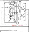
Practical case (please see attachment):
- D is a -45V line, it seems that the board should draw 32mA
- E is a +45V line, it seems that the board should draw 32mA
- after recapping, I want to put one DBT where D is, and another on E is, at the first power on
- so i guess i need to do some computations about the most suitable bulb params (at least in tems of wattage).
How should I proceed?

Also, regarding the power test:
- should I do power up tests in stages, like: power up with all other inputs and outputs disconnected / then power up connecting inputs / power up connecting outputs, in order to contain the potential cascade failure?
- what could be the implications for the boards such having the open-air outputs / inputs, in the audio chain?

I know is time consuming, but is a personal project on a personal amp, so I'm looking for the best practice model - time is not a problem.
As for now, the amp works without problems, but a visual check revealed some ticking bombs, thus I want to start the recap project, as safe as possible
 

Attachments

  • example.jpg
    example.jpg
    134.5 KB · Views: 6
Last edited:
I thought that one connect the bulb in series with the board itself - i.e. if one executes some maintenance operations on a single board, which is powered with a +/- 45V voltage; then one connect the bulb in series with the board supply power inputs, and it powers up from the +/- 45V rails.
So I was starting to thinking on Ohm laws - how to choose the bulb params thus to assure a sufficient current limitantion (high current protection), and how the voltage drop on the bulb may affect the final voltage reaching the board.
You would be, as far as I know, the only one to do this. Hundreds, even thousands of Tech's use either a mains DBT with (for an AU-717), either a 60W or 100W bulb, or a Variac or both. We can help you with what to expect using a DBT, but to help you if you put bulbs in series with the internal supply rails - we will just be guessing at answers for some of the weird problems you are almost certain to encounter.

You may think your idea is a more intelligent, cleverer way to approach this, but remember the use of a DBT is only for discovery of shorts and high current situations, which are otherwise harder to track down. Experience has shown the mains DBT to be perfect for this, and I think you are going to use a lot of small bulbs by doing it your way.

My Advice
I strongly advise you to use a mains DBT for SS equipment, and for Valve (Tube) gear a Variac, augmented in some cases by the use of a DBT as well.

 
Last edited:
You would be as far as I know, the only one to do this. Hundreds, even thousands of Tech's use either a mains DBT with (for an AU-717), either a 60W or 100W bulb, or a Variac or both. We can help you with what to expect using a DBT, but to help you if you put bulbs in series with the internal supply rails - we will just be guessing at answers for some of the weird problems you are almost certain to encounter.

You may think your idea is a more intelligent, cleverer way to approach this, but remember the use of a DBT is only for discovery of shorts and high current situations, which are otherwise harder to track down.

My Advice
I strongly advise you to use a mains DBT for SS equipment, and for Valve (Tube) gear a Variac, augmented in some cases by the use of a DBT as well.

As context, I do this as hobby and also I'm new in approaching the electronics domain at this level.
Thus, lately I absorbe information (i.e. I was just reading on another thread that someone uses car lightbulbs when powering lower voltage boards, to test them), and try to fully undestand the things.
So I consider this affirmation very valuable for me, as a clarification of DBT use:
but remember the use of a DBT is only for discovery of shorts and high current situations, which are otherwise harder to track down.
Thank you!
 
remember the use of a DBT is only for discovery of shorts and high current situations, which are otherwise harder to track down
Exactly! Many of us are familiar with the behavior of our favorite DBT light bulb filament under extreme conditions, and with specific units. It's great for detecting short circuits, undesired oscillations, and it mostly serves for indicating a good, and healthy amp behavior. We know exactly how dim it should look like. Take away the 'extreme' and start using a DBT for low current draw, in the smaller tens of mA, and the filament won't even light up - rendering the idea of a 'dim bulb' useless.
 
Hello friends, greetings, I can't find these transistors that go in the power supply TR05-TR06 and TR09-10 – 2SC1708 / Now KSA992FB
TR07-TR08 and TR11-12 – 2SA847 / Now KSC1845FB
appear in the web stores is the KSC1845FTA, KSA992FTA which offer less hfe gain compared to those suggested in the list that you can recommend to me
 
Hello friends, greetings, I can't find these transistors that go in the power supply TR05-TR06 and TR09-10 – 2SC1708 / Now KSA992FB
TR07-TR08 and TR11-12 – 2SA847 / Now KSC1845FB
appear in the web stores is the KSC1845FTA, KSA992FTA which offer less hfe gain compared to those suggested in the list that you can recommend to me
I used KSC1845FTA and KSA992FBTA in my personal AU-717.

It's always a good bet to try octopart.com when you're trying to find something specific. E.g. https://octopart.com/search?autosugg_idx=1&q=ksa992fb

Also, starting your own thread instead of asking a new question in an old thread is probably better.
 
I used KSC1845FTA and KSA992FBTA in my personal AU-717.

It's always a good bet to try octopart.com when you're trying to find something specific. E.g. https://octopart.com/search?autosugg_idx=1&q=ksa992fb

Also, starting your own thread instead of asking a new question in an old thread is probably better.
Thanks for your reply. The one that cannot be found is the KSC1845FB in web stores which matches the KSA992FB. My question is if there is no problem in combining the FT and the FB having different hfe gain between them or is it preferable to put the pair KSC1845FTA, KSA992FTA
 
Hello friends, greetings, I can't find these transistors that go in the power supply TR05-TR06 and TR09-10 – 2SC1708 / Now KSA992FB
TR07-TR08 and TR11-12 – 2SA847 / Now KSC1845FB
appear in the web stores is the KSC1845FTA, KSA992FTA which offer less hfe gain compared to those suggested in the list that you can recommend to me
They, F or FB will be fine. The gain won't be an issue.
 
In the rebuild summery are some mixups with the pnp/npn transistors on the PS board.

In the summary:
TR05-TR06 & TR09-10 – 2SC1708 / Now KSA992FB
TR07-TR08 & TR11-12 – 2SA847 / Now KSC1845FB

should be the other way around.
 
Back
Top Bottom