You are using an out of date browser. It may not display this or other websites correctly.
You should upgrade or use an alternative browser.
You should upgrade or use an alternative browser.


Tim D
Super Member
Well, here is the plot of the impedance. Other than to note it and wonder what this does with the interaction of the amplifier I don't know what else to say about the drop in impedance. This is the result of not having a cross-over on the woofer. I.e. It keeps receiving signal all the way up through its' breakup region and the amp would see a drop in impedance. Is this harmful? Don't think so. Does it have an audible impact? I don't know, but I have to believe the amps/receivers aren't designed with non-linear loads in mind.
Tim D
Super Member
To keep things cheap and to stay away from the breakup region on the woof, I'm going to make the first attempt at the original cutover frequency of ~1325Hz. I'll keep the original cross-over in place on the tweeters and add a similar cross-over to the woofer. I.e. Same size inductor (1mh) and same size capacitor (1ufd) as the stock components no the tweeter. Here is a pic of an online calculator which matches with a 2nd Order Chebychev Q=1 at 1325Hz. I'm adding the components to the woofer and leaving the original cross-over on the tweeter. Please note that the Nova 7B has two 16 ohm tweeters in parallel which gives an effective impedance of 8 ohms which I inputted into the tool. Let me know if you want the URL for the calculator.
Here's the new cross-over I'm going to try. I've ordered parts from PE for this and they should arrive in a week. The plan is to measure the response and impedance curves of the new cross-over and I'll give a subjective opinion when I listen to them. If it doesn't turn out good enough I'll try something different. Note that this first attempt is just to try to reuse what was already in place. I believe that the original designers thought that 1325Hz was a good place for the cross-over so we'll start there.
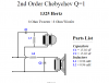
Here's the new cross-over I'm going to try. I've ordered parts from PE for this and they should arrive in a week. The plan is to measure the response and impedance curves of the new cross-over and I'll give a subjective opinion when I listen to them. If it doesn't turn out good enough I'll try something different. Note that this first attempt is just to try to reuse what was already in place. I believe that the original designers thought that 1325Hz was a good place for the cross-over so we'll start there.

phansen39
Active Member
Tim D Have you read Jeff Bagby's white paper on speaker measurement?
http://audio.claub.net/software/FRD_Blender/White Paper - Accurate In-Room Frequency Response to 10Hz.pdf
For a 2 way speaker 5 measurements are taken. For a 3 way 7 measurements.
When measuring start with farfield measure of the tweeter. You want a windowed impulse response. This will remove the room reflections
More on gated windows
http://mike.seddon.ca/loudspeaker-frequency-response-measurement/
Basically far field measurements of each driver keeping the microphone in same position inline with the tweeter. Then a combined measurement of all drivers still keeping mic a same position
After the far field. nearfield measurement of each separate driver No windowing
Load the nearfield and farfield measurements into frd blender and combine and extract minimum phase. Frd blender is for getting a better LF response. It is also good at manipulating the db levels and of course extracting minimum phase.
Now use you favorite cross over program and load the combined frd and zma for each driver.
You should also have a farfield measurement of the combined drivers. Its purpose is to help alignment.
You paste it as an overlay and the adjust the x,y,z of the driver till the plot looks as close as you can get it.
See the plot below. you see 2 lines one is the combined measurement the other is the woofer and tweeter after aligning x,y,z. The big dip at 5k is a shelf in the room I did the measurement in. In this case my farfield measurement was to far away and my window on the impulse response to long.
http://audio.claub.net/software/FRD_Blender/White Paper - Accurate In-Room Frequency Response to 10Hz.pdf
For a 2 way speaker 5 measurements are taken. For a 3 way 7 measurements.
When measuring start with farfield measure of the tweeter. You want a windowed impulse response. This will remove the room reflections
More on gated windows
http://mike.seddon.ca/loudspeaker-frequency-response-measurement/
Basically far field measurements of each driver keeping the microphone in same position inline with the tweeter. Then a combined measurement of all drivers still keeping mic a same position
After the far field. nearfield measurement of each separate driver No windowing
Load the nearfield and farfield measurements into frd blender and combine and extract minimum phase. Frd blender is for getting a better LF response. It is also good at manipulating the db levels and of course extracting minimum phase.
Now use you favorite cross over program and load the combined frd and zma for each driver.
You should also have a farfield measurement of the combined drivers. Its purpose is to help alignment.
You paste it as an overlay and the adjust the x,y,z of the driver till the plot looks as close as you can get it.
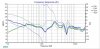
See the plot below. you see 2 lines one is the combined measurement the other is the woofer and tweeter after aligning x,y,z. The big dip at 5k is a shelf in the room I did the measurement in. In this case my farfield measurement was to far away and my window on the impulse response to long.
Attachments
Last edited:
Tim D
Super Member
Tim D Have you read Jeff Bagby's white paper on speaker measurement?
http://audio.claub.net/software/FRD_Blender/White Paper - Accurate In-Room Frequency Response to 10Hz.pdf
For a 2 way speaker 5 measurements are taken. For a 3 way 7 measurements.
When measuring start with farfield measure of the tweeter. You want a windowed impulse response. This will remove the room reflections
More on gated windows
http://mike.seddon.ca/loudspeaker-frequency-response-measurement/
Basically far field measurements of each driver keeping the microphone in same position inline with the tweeter. Then a combined measurement of all drivers still keeping mic a same position
After the far field. nearfield measurement of each separate driver No windowing
Load the nearfield and farfield measurements into frd blender and combine and extract minimum phase. Frd blender is for getting a better LF response. It is also good at manipulating the db levels and of course extracting minimum phase.
Now use you favorite cross over program and load the combined frd and zma for each driver.
You should also have a farfield measurement of the combined drivers. Its purpose is to help alignment.
You paste it as an overlay and the adjust the x,y,z of the driver till the plot looks as close as you can get it.
See the plot below. you see 2 lines one is the combined measurement the other is the woofer and tweeter after aligning x,y,z. The big dip at 5k is a shelf in the room I did the measurement in. In this case my farfield measurement was to far away and my window on the impulse response to long.
Wow phansen39. That's the kind of help I need! I'm reading and trying to digest it. Seems that the first whitepaper is about specific new methods for obtaining the system response from various separate measurements. I.e. Splicing near and far field measurements using a new methodology for joining the results. Lotsa good info. I'm now moving on to the second source to read. Thanks!
You seem to know a lot about this method. Were you involved in writing the paper or have you been using this methodology in your own projects? Are you a professional?
phansen39
Active Member
No I'm kinda new to speaker crossover design myself. But I've been reading and experimenting alot. Mostly figured out how to do jeff bagby's technique correctly. Many many evenings of experimentation and learning ways that don't measure correctly. Like that response plot above. That dip at 5 khz is a measurement error. Measured the room not the speaker. Jeff bagby's method seems to work quite well. Just takes a bit of playing. Expecially with the windowed impulse response. If the nearfield and farfield looks very similar. No major dips or peaks between the 2 measurements you probably have a good measurment.
Tim D
Super Member
No I'm kinda new to speaker crossover design myself. But I've been reading and experimenting alot. Mostly figured out how to do jeff bagby's technique correctly. Many many evenings of experimentation and learning ways that don't measure correctly. Like that response plot above. That dip at 5 khz is a measurement error. Measured the room not the speaker. Jeff bagby's method seems to work quite well. Just takes a bit of playing. Expecially with the windowed impulse response. If the nearfield and farfield looks very similar. No major dips or peaks between the 2 measurements you probably have a good measurment.
All good. Let's do this together. Do you recommend that I re-measure the Nova 7B's using Bagby's methodology? My goal is to update the cross-over. I am hoping to continue to use the stock drivers. Any questions about my rig? Here's a summary of where I think I am.
The stock speaker has the woofer running free. This drives the woofer through its' breakup region and I think it adds a conflicting point source of mid-range frequencies which will add to lobbing.
I think I've shown where the breakup region is and I think I've shown that the breakup region is preventing the midrange response from being smooth. The options for a new crossover frequency are limited to some band below where the breakup occurs. I would also not think we want the cross-over to go any lower than the current 1325Hz.
I have not tackled the phase behavior in any way. I've shown that running the woofer free drops the impedance above the cross-over frequency precipitously. Not sure this is a problem, but I have concerns that this isn't desirable.
Any comments on any of this? So if I remeasure would the goal be to get data to input into cross-over tools to pick a cross-over type and cross-over frequency?
phansen39
Active Member
I don't think it would hurt to remeasure if you want.
That impedance measure you did was that a system measurement. woofer, tweeters and crossover?
Could be from the 1mH inductor to ground. Kind of odd that it would have a 2pole on the tweeters an free running on the woofer.
Well a full measurement will tell the story.
That impedance measure you did was that a system measurement. woofer, tweeters and crossover?
Could be from the 1mH inductor to ground. Kind of odd that it would have a 2pole on the tweeters an free running on the woofer.
Well a full measurement will tell the story.
Tim D
Super Member
I don't think it would hurt to remeasure if you want.
That impedance measure you did was that a system measurement. woofer, tweeters and crossover?
Could be from the 1mH inductor to ground. Kind of odd that it would have a 2pole on the tweeters an free running on the woofer.
Well a full measurement will tell the story.
Yes, the impedance measurement was the entire stock speaker cabinet. It was measured from the terminals on the back using the Dayton Audio "DATS" program. In terms of the impedance dropping down to 5 ohms on the graph, that didn't surprise me because of the way these are wired in the cross-over. The two 16 ohm tweeters are wired in parallel and the woofer is wired in parallel with the tweeters. Of course the tweeters are behind the cross-over, but above the cross-over frequency that cross-over disappears meaning all 3 drivers are in parallel. If you do the math that drops the nominal impedance to 4 ohms. That's not far off the 5 ohms I measured. I'm thinking that ideally we'd want the impedance to be flat, but I wish an expert would chime in to say how important that is (or not).

Been enjoying and following this thread. Entertaining notions of modding my own Nova-7Bs and would love to play along. Got other projects hot on the burner at the moment though -- I'll hafta catch up with you all at a later time.
Noticed a stock crossover schematic I worked up for another thread was revisited here in post #16. I made the unfortunate choice to draw it somewhat similar to how the actual crossover is laid out, hoping that might help someone tracing their physical crossover wiring. Turned out to be confusing instead.
I've since sketched another in more conventional form. This thread has gathered a following, suggesting no small interest in modding these things. Seems a good place to post the improved schematic, should anyone need a (better) reference for how these crossovers started life from the factory.
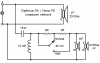
Noticed a stock crossover schematic I worked up for another thread was revisited here in post #16. I made the unfortunate choice to draw it somewhat similar to how the actual crossover is laid out, hoping that might help someone tracing their physical crossover wiring. Turned out to be confusing instead.
Ok. I found a diagram. (Reference from AK member "Stuart Pedaso" on ,Sep 11, 2015 in thread http://audiokarma.org/forums/index.php?threads/realistic-nova-7b-any-crossover-mods.677937/)View attachment 804890 ). This is a good place to start.
I've since sketched another in more conventional form. This thread has gathered a following, suggesting no small interest in modding these things. Seems a good place to post the improved schematic, should anyone need a (better) reference for how these crossovers started life from the factory.
Last edited:
Tim D
Super Member
Been enjoying and following this thread. Entertaining notions of modding my own Nova-7Bs and would love to play along. Got other projects hot on the burner at the moment though -- I'll hafta catch up with you all at a later time.
Noticed a stock crossover schematic I worked up for another thread was revisited here in post #16. I made the unfortunate choice to draw it somewhat similar to how the actual crossover is laid out, hoping that might help someone tracing they're physical crossover wiring. Turned out to be confusing instead.
I've since sketched another in more conventional form. This thread has gathered a following, suggesting no small interest in modding these things. Seems a good place to post the improved schematic, should anyone need a (better) reference for how these crossovers started life from the factory.
View attachment 864322
Nice diagram. Thanks. It clearly shows the woofer runs free. Also note that when the tweeter switch is in "High" that the two tweeters are in parallel and only separated from the woofer by the cross-over. I'm just saying.......
Last edited:
To keep things cheap and to stay away from the breakup region on the woof, I'm going to make the first attempt at the original cutover frequency of ~1325Hz. I'll keep the original cross-over in place on the tweeters and add a similar cross-over to the woofer. I.e. Same size inductor (1mh) and same size capacitor (1ufd) as the stock components no the tweeter. Here is a pic of an online calculator which matches with a 2nd Order Chebychev Q=1 at 1325Hz. I'm adding the components to the woofer and leaving the original cross-over on the tweeter. Please note that the Nova 7B has two 16 ohm tweeters in parallel which gives an effective impedance of 8 ohms which I inputted into the tool. Let me know if you want the URL for the calculator.
Here's the new cross-over I'm going to try. I've ordered parts from PE for this and they should arrive in a week. The plan is to measure the response and impedance curves of the new cross-over and I'll give a subjective opinion when I listen to them. If it doesn't turn out good enough I'll try something different. Note that this first attempt is just to try to reuse what was already in place. I believe that the original designers thought that 1325Hz was a good place for the cross-over so we'll start there.
View attachment 862945
I'm curious if you've measured and plotted impedance curves for the raw drivers. Any driver with a voice coil (inductor) will have impedance that varies with frequency -- often by a lot (even discounting the large peak that occurs for other reasons at resonance). When designing a filter it's good to know the driver's impedance at the desired corner frequency.
If the paralleled tweeters' impedance actually measures 8Ω at 1325Hz, it would support the conclusion that this was the filter designer's target and that (based on component values in situ) a 2nd order Chebychev filter was chosen.
But what of the woofer? If luck is kind and it also measures 8Ω at 1325Hz then you're golden. But what if it's 10Ω, ... or 16Ω? The components you ordered wouldn't provide the response you want at the frequency you expect. Once a driver's minimum impedance is reached after resonance, impedance rises with frequency -- it's what an inductor does. Plugging "nominal" impedance into an online crossover calculator can't be expected to return accurate results unless the driver just happens to measure that impedance at the target frequency.
Installing even random value series inductor and parallel cap in the woofer circuit will certainly create a low pass filter. Might even reduce interference with tweeter and improve overall performance. But without better informed choice of crossover component values, you may not achieve the optimum results you're shooting for. There are a variety of parameters to consider and individual driver impedance curves seems a good place to start.
Last edited:
Tim D
Super Member
I'm curious if you've measured and plotted impedance curves for the raw drivers. Any driver with a voice coil (inductor) will have impedance that varies with frequency -- often by a lot (even discounting the large peak that occurs for other reasons at resonance). When designing a filter it's good to know the driver's impedance at the desired corner frequency.
If the paralleled tweeters' impedance actually measures 8Ω at 1325Hz, it would support the conclusion that this was the filter designer's target and that (based on component values in situ) a 2nd order Chebychev filter was chosen.
But what of the woofer? If luck is kind and it also measures 8Ω at 1325Hz then you're golden. But what if it's 10Ω, ... or 16Ω? The components you ordered wouldn't provide the response you want at the frequency you expect. Once a driver's minimum impedance is reached after resonance, impedance rises with frequency -- it's what an inductor does. Plugging "nominal" impedance into an online crossover calculator can't be expected to return accurate results unless the driver just happens to measure that impedance at the target frequency.
Installing even random value series inductor and parallel cap in the woofer circuit will certainly create a low pass filter. Might even reduce interference with tweeter and improve overall performance. But without better informed choice of crossover component values, you may not achieve the optimum results you're shooting for. There are a variety of parameters to consider and individual driver impedance curves seems a good place to start.
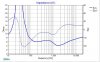
All good info Stuart. I'll individually measure the impedance of the drivers and post them here. That's going to be easy with the DATS package. I'm digesting everyones inputs and will continue to measure and respond.
Tim D
Super Member
Good point. The circuit does show the inductor in parallel with the tweeters. Above the crossover freq the impedance of that inductor is going to get big fast. While it shouldn't be totally ignored, for rough purposes it isn't going to affect the overall impedance of the system by much at high frequencies. I.e. It will look like an open circuit at high frequencies.

phansen39
Active Member
Can't read it.Looks impedanse at 1 k is about 22 ohms.
In DATS Export the impedance measurements as a zma. Post the zma
At a minimum get separate (tweeters and woofer) farfield impulse responses and export as an frd
Better would be nearfield and farfield and combined farfield. Export the impulse response as a wav. It will us play with the windowing of impulse response.
In DATS Export the impedance measurements as a zma. Post the zma
At a minimum get separate (tweeters and woofer) farfield impulse responses and export as an frd
Better would be nearfield and farfield and combined farfield. Export the impulse response as a wav. It will us play with the windowing of impulse response.
Tim D
Super Member
Can't read it.Looks impedanse at 1 k is about 22 ohms.
In DATS Export the impedance measurements as a zma. Post the zma
At a minimum get separate (tweeters and woofer) farfield impulse responses and export as an frd
Better would be nearfield and farfield and combined farfield. Export the impulse response as a wav. It will us play with the windowing of impulse response.
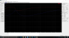
Sorry. I'm doing this in stages. I intend on digging deeper and given time I'll get to the part you are referring. I'm doing baby steps right now. Let's try this again. I've zoomed a bit and cropped it to try to increase the resolution. Here is the tweeter. I've got the frequency range of zero to 2k showing. The impedance shows in the neighborhood of 15 to 16 ohms except for the resonant frequency bump around 400Hz. If this still doesn't look good let me know and I'll try something else. This is just to narrow down the impedance response of the tweeter driver.
Note that the speaker Nova 7B has two of these in parallel, so the actual impedance of the pair is half. I.e. About 7.5 to 8 ohms. For frequencies above 2kHz the impedance slopes upwards. I would use the value of 8 ohms in the cross-over calculator in my first attempt. (Mostly because I already bought the parts.)