• The move to the new server is done. There are some software and database maintenance updates in process. This has us passing the hat around to help out. We appreciate any donations. Seriously, even a dollar helps. The payment page may be found here - https://www.audiokarma.org/support.html

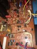
Recapping a Tandberg TR-2080

Nope. Those are modern subs. The originals have a flat metal band slotted into one side of the resistors that helps brace the resistor mounting and also doubles as a connection path for the upper end. I missed that in the pics, but for sure they've been replaced. You can kind of see what they were originally here (this is a 2075 MkII but same resistors):

2ykthgez1lgh.jpg


What does it have in it for outputs and driver transistors? S/B 2N5630/2N6030 Motorola's with late 70's/early 80's production dates for the outputs, drivers had a couple of variations depending on when it was built.

John
 
Nope. Those are modern subs. The originals have a flat metal band slotted into one side of the resistors that helps brace the resistor mounting and also doubles as a connection path for the upper end. I missed that in the pics, but for sure they've been replaced.

. . .

What does it have in it for outputs and driver transistors? S/B 2N5630/2N6030 Motorola's with late 70's/early 80's production dates for the outputs, drivers had a couple of variations depending on when it was built.

John

This unit came to me with modern OnSemi outputs.

IMG_8400.JPG
 
I've used those as well, no issue with that although I try and recycle spare originals from donor pieces where I can. Did they sub for the drivers too? Usually this means one or more outputs has been blown and if that's the case, would explain the emitter resistors (usually lose one at least if an output shorts) and drivers are next upstream...

John
 
I've used those as well, no issue with that although I try and recycle spare originals from donor pieces where I can. Did they sub for the drivers too? Usually this means one or more outputs has been blown and if that's the case, would explain the emitter resistors (usually lose one at least if an output shorts) and drivers are next upstream...

John

I hadn't examined the drivers on the power amp board yet. No real reason to up to this point.

The small signal transistors everywhere else are BC5xx devices, just what I'd expect in this unit.

Now you've got me worried, so I'll have to dig deeper into the power amp components. I don't want to blow any amount of $60 of new caps due to a blown $3 resistor or $0.21 transistor....
 
A word of caution with this particular Tandberg. The circuit path traces do not like much heat. They lift pretty quickly with what I'd call a typical (Hakko FR-330) desoldering iron heat level.

:(
Since someone has been in this receiver already I would expect traces to lift. I've been using high heat epoxy on lifted traces to great effect (very small amounts with a toothpick size metal pick).
Chang, how funny, there's also a beer named Chang. Note, Chang was the name of the caps that were cooked in my Abit and Asus computer motherboards during the capacitor plague.
 
Dear dear friend, I have no idea where you got that machine. But I SWEAR THAT TANDBERG NEVER EVER USED that kind of CRAP in any of their products.
even the ones made in Asia in the later years had better parts in it.
Someone definitely has been working on that thing. I guess that is why it is looking that bad.

BTW Chang is a Thai beer nor bad either
and furthermore Chang means Elephant in Thai

What I meant to say about the professionalism of the Tandberg engineers is that they make TOTL Products, though they use only standard parts (not TOTL parts)

but I see you are not finished soon yet
 
@jdurbin1 and @fernarias : do you have a hires scan of the power amp board schematic? Or even just a parts list? I can't read the device model numbers of the transistors in the lowres scan of the service manual....
 
The driver transistors Q923-926 are MJE15030 and MJE15031, modern devices... so I'm guessing those aren't OEM either.

There are also modern Bournes trimpots with jumpers legs. Someone has definitely been working on this power amp board before.

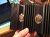
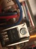
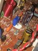
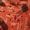
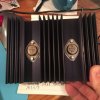
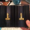
IMG_8503.JPG IMG_8504.JPG IMG_8510.JPG IMG_8511.JPG
 
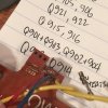
So, after cataloging the transistors on the power amp board, this is what I've got in this unit. You Tandberg experts, please help with where these deviate from the proper parts. The scanned service manual doesn't seem to list parts, so I'm counting on you to help me, please.

Q901+Q903,Q902+Q904 are these 2SC1583 they are definitely a pair in a single device
Q905,Q917,Q906,Q918 BC558C
Q907,Q911,Q908,Q912 2SB528 (these really need their own heatsinks)
Q909,Q910 BF381 (these really need their own heatsinks)
Q913,Q914 BC548B (under the output transistors' rear bracket, on the heatsink)
Q915,Q916 BC548C
Q919,Q920 BC546B
Q921,Q922 BC556B
Q923,Q924 FT317A (with screw-on heatsink) and mine have MJE15030 in their place
Q925,Q926 FT417A (with screw-on heatsink) and mine have MJE15031 in their place
Q927,Q928 2N5630 (the outputs) (mounted to tall pairs heatsink)
Q929,Q930 2N6030 (the outputs) (mounted to tall pairs heatsink)

Q971,Q973,Q974 BC547A
Q975 BC557A
Q972 BC548C

Help me find the right part numbers or verify the above and I'll keep the list here up-to-date.
 
Last edited:
For the output transistors, the 2n5630 and 2n6030, there are good number of options (as per this thread) as per @markthefixer :

OnSemi:

MJ15003G NPN 140V 20A 250W
MJ15022G NPN 200V 16A 250W
MJ15024G NPN 250V 16A 250W
MJ21194G NPN 250v 16A 250W


MJ15004G PNP 140V 20A 250W
MJ15023G PNP 350V 16A 250W
MJ15025G PNP 400V 16A 250W
MJ21193G PNP 250v 16A 250W

the 2119x's are the latest technology, and as to price it's a toss up at about 4 to 5 bucks each at digikey or mouser. ALL are TO-3 cases.
EW generally goes for the MJ21193, MJ21194's... don't forget the "G" or they'll come up unstocked, as the non-G has lead and the new ROHS compliant ones have the "G".
 
The better resolution schematic in the online archive is for the Norway version 2075 MkII: http://sportsbil.com/tandberg/tr-2075mkii-s.pdf

I do have a better scan of the later 2075 MkII/2080 manual at home (and the originals for all of these), but it's a little big for email.

Keep in mind there is sort of a continuum for these models: 2075 (early), 2075 (later, with new IF solution), 2075 MkII (early, similar to late 2075), 2075 MkII (late, same as 2080 except for amber display). The service literature available tracks some of that but with a few holes.

The 2075 service manual is a prettty good reference for all 2075 models but you have to parse the IF section and use the one suitable for that version. Watch out for updated boards with higher board numbers than the ones indicated in the service manual drawings, may see some component value variances on those. They screwed around a little with the power switch & nearby components in there, and I've run into a resistor value change that was preventing the protection relay from operating on a receiver that had apparently mismatched source/regulator board vs. power amp board.

Early 2075 MkII follow the linked schematic file above. The value of the volume control pot should tell you whether it's early or late (one's 25K, the other 50K IIRC).

Later 2075 MkII follow the combined 2075 mkII/2080 service manual but again be on the watch for an occasional board number variant. The 2080 stayed in production for years and the early 2075 went through a lot of running change/continuous improvement by the engineers, and the MkII was a transition model so even in its short lifespan there were changes.

Those subs are ok, can't remember which of the OnSemi output sets I picked last time but there's plenty of advice on that elsewhere on AK as you cite above. I will say I do a much neater job on that Bourns pot leg extension, though - you'd have to really get close to spot it. I use the 15-turn part, 25 is just way more than is needed here for a reliable stable adjustment.

2SC1583 is correct per that linked schematic. They used part number MD 8003 in the older 2075 models. Some discussion on those parts here: http://audiokarma.org/forums/index.php?threads/help-with-dual-npn-device-substitute.256808/

BC transistors will be originals, or at least correct type - hard to say sometimes whether someone has subbed a later improved version or if it's just a newer board that the manual doesn't track exactly.

John

 
Last edited:
Looking around AK, it sounds like some folks have replaced the 2SC1583 with a pair of 2SC2240's, KSC1845's, BC639-16's, or BC550's.

The 2SC2240's are no longer made, the KSC1845's handle too little current (50 mA instead of 100mA), and the BC639-16's are backordered.

(Note: a pair of KSC1845's were used in this thread)

Looking at the Low Noise Transistor list, it looks like SS9014 or BC550 would be the best available choice, so I'm going with a pair of BC550 for each 2SC1583. I'll have to twist the leads a bit....
 
Last edited:
Assume you will tie them together physically so they share thermal? Will be interested in the outcome, I've not had to replace that part (so far, knock wood) but only because I almost always have a good working spare part on hand. Good to have modern replacement parts sorted out.

John
 
Looking around AK, it sounds like some folks have replaced the 2SC1583 with a pair of 2SC2240's, KSC1845's, BC639-16's, or BC550's.

The 2SC2240's are no longer made, the KSC1845's handle too little current (50 mA instead of 100mA), and the BC639-16's are backordered.

(Note: a pair of KSC1845's were used in this thread)

Looking at the Low Noise Transistor list, it looks like SS9014 or BC550 would be the best available choice, so I'm going with a pair of BC550 for each 2SC1583. I'll have to twist the leads a bit....
KSC945CGTA everything fits except for gain unless you can find the high gain 945.
Sorry, don't have the service manual. I have a 2275 waiting it's turn and found this thread interesting.
 
Looking around AK, it sounds like some folks have replaced the 2SC1583 with a pair of 2SC2240's, KSC1845's, BC639-16's, or BC550's.

The 2SC2240's are no longer made, the KSC1845's handle too little current (50 mA instead of 100mA), and the BC639-16's are backordered.

(Note: a pair of KSC1845's were used in this thread)

Looking at the Low Noise Transistor list, it looks like SS9014 or BC550 would be the best available choice, so I'm going with a pair of BC550 for each 2SC1583. I'll have to twist the leads a bit....
Although I have those BC547 and BC550 also, they are rather run out of safety margin (Vceo 45V max, Vcbo 50V), since in the circuit they get around 51 volts already.

As the input transistors use 1 milliamp each, the fact KSC1845 can only handle 50 does not matter, that is why I did see no problem using them and so I did.

Assume you will tie them together physically so they share thermal? Will be interested in the outcome, I've not had to replace that part (so far, knock wood) but only because I almost always have a good working spare part on hand. Good to have modern replacement parts sorted out.

John
Myself I assumed it not needed, they use same current and voltage so they dissipate the same. I think thermal connection through legs and circuit card is enough.
BTW you get tighter tolerance matching KSC transistors of same batch compared to average old dual transistor...
 
Last edited:
Although I have those BC547 and BC550 also, they are rather run out of safety margin (Vceo 45V max, Vcbo 50V), since in the circuit they get around 51 volts already.

As the input transistors use 1 milliamp each, the fact KSC1845 can only handle 50 does not matter, that is why I did see no problem using them and so I did.

Great points! KSC1845 it is, then!
 
I'd still bind them. Tandberg did the same on later pieces where they were using a pair of small transistors in a combined circuit like that. Granted, it was part of their feed-forward thermic loop design which may have been less tolerant of heat differential at that stage of the circuit. A bit of thermal grease, flat sides pressed together, and a piece of shrink tube to hold them that way. Not sure if that's as easy to do with the board layout on the 2080, though.

John
 
After pulling and testing ALL the resistors, ALL the caps, and ALL of the transistors on the power amp board, I've found the culprit: the BC558C at Q918 was bad, causing distortion in just that channel and only in the output stage. So, I'll replace all the resistors with high precision metal films, all the caps with Panasonic ECQ films, and all the transistors with new production BC5xx series.

IMG_8627.JPG

There were several larger transistors that tested fine but which had made distinct, dark burn marks on the PCB. Those positions will get beefier replacements with heatsinks. These were the BF381 devices at Q909,Q910 and the 2SB528 devices at Q907,Q908,Q911,Q912.

IMG_8621.JPG

I'll pull all the diodes and test and replace them while I'm in there. Some of them have definitely been replaced by someone after it left the factory. There sure are a lot of diodes in this design. I do wonder why that is.

IMG_8613.JPG
 
Last edited:
Well, this Tandberg continues to be a great learning experience. Whether you see the design bits as genius or overly-complicated is a matter of opinion. ;)

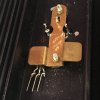
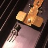
While triple-checking the transistor list for the power amp board, I realized I was missing Q913 and Q914. I'd carefully desoldered ALL the devices from power amp board, cataloged them, added in the four output transistors mounted on the two heatsinks... but the schematic showed two more transistors I had not found.

Oh, right... there are two connectors on the back edge of the board that accept three pin devices... tacked under the output transistor mounting bracket. Don't forget THESE!

IMG_8639.JPG
IMG_8640.JPG
IMG_8641.JPG
IMG_8642.JPG
IMG_8646.JPG
IMG_8647.JPG
IMG_8653.JPG
 
Back
Top Bottom