• The move to the new server is done. There are some software and database maintenance updates in process. This has us passing the hat around to help out. We appreciate any donations. Seriously, even a dollar helps. The payment page may be found here - https://www.audiokarma.org/support.html

Recapping and restoring a Harman Kardon 330C

The $15 amazon one was about +5hFE higher on all transistors. I'm not sure if this is a problem but i was able to pick the closest ("matching") ones with both tools.

The cheap component testers probably use a different testing voltage than the Atlas Peak devices. Testing at different voltages would yield different gain levels.
 
This is the one I picked up-

https://www.amazon.com/gp/product/B071Y5CHPK/ref=oh_aui_detailpage_o00_s00?ie=UTF8&psc=1

I almost got one of the ones mentioned in Doug's thread but this one seemed to do what I need and it was $15 cheaper. I figure I can test and retest a bunch, and as long as it's measuring consistent values even if the hFE is a little off I'll be able to match like values.

For the heck of it I'm also going to test the capacitors as well, I should be able to compare the average deviation and see if it's close. Although from the reviewers that had access to better testing equipment most found the unit to be pretty accurate.
 
Thank you again Doug!! You've been an incredible help. I was also checking out your Noisy Transistors You Should Replace list and ordered 100 of the KSC1845 for $8 that will work for 2 sets of transistors. Really appreciate all the great advice.

While you were at it, you should have ordered its complement...KSA992. It gets used an awful lot too as a replacement for many of the 2SA...low-noise low signal preamp transistors.
 
While you were at it, you should have ordered its complement...KSA992. It gets used an awful lot too as a replacement for many of the 2SA...low-noise low signal preamp transistors.

I feel like I will be spending a lot on Mouser shipping... The other one I plan to replace is the SC458 for the bias stabilization. A lot of places list the KSC1845, Doug's list call out KSC1845E or KSC1845F but they're not available.

I'll have both of these on hand, will either work? I can rework the pin locations. Seems like the biggest difference is the gain? Is there an ideal hFE?

KSC1845 https://www.mouser.com/ProductDetail/512-KSC1845FTA

or

BC550 https://www.mouser.com/ProductDetail/512-BC550CBU
 
I feel like I will be spending a lot on Mouser shipping... The other one I plan to replace is the SC458 for the bias stabilization. A lot of places list the KSC1845, Doug's list call out KSC1845E or KSC1845F but they're not available.

I'll have both of these on hand, will either work? I can rework the pin locations. Seems like the biggest difference is the gain? Is there an ideal hFE?

KSC1845 https://www.mouser.com/ProductDetail/512-KSC1845FTA

or

BC550 https://www.mouser.com/ProductDetail/512-BC550CBU


The actual device model is KSC1845. The "E" and "F" are the gain codes. So, the KSC1845 is a basic design and the manufactured ones fall within a gain range of gain, they are assigned a gain code.

In general you can search at an online catalog by just the part number. Once you have results, if you have more than one gain code offered you can sort or pick and choose. In general, higher gain is better.

So, for instance you've decided you want a KSC1845. Just search for "KSC1845". When you get back part numbers in KSC1845E and KSC1845F, just pick the one you like best by price or gain and order that.

The trailing letters of "TA" or "BU" in a part number like "KSC1845FTA" are not the gain code, but rather the packaging style. Like "TA" stands for "cut tape" and "BU" stand for "bulk". The part itself is still a KSC1845 with a gain code of "F".
 
St
The cheap component testers probably use a different testing voltage than the Atlas Peak devices. Testing at different voltages would yield different gain levels.
Been doing more reading and starting to understand what you mean by this, as I understand a cheaper unit may not test at the voltage the transistor will actually operate at so the value is not really accurate.

I can't figure out whether that's the case though, in the Cheap Components Thread the tester in the first post compared the TC-1 to the Atlas and found them within 1%. I don't see doing a lot of these, so the Atlas would be a one-time use. If I want to do it right, should I just get the Atlas? Or the TC-1 at $30? I'm leaning towards the Atlas just for the peace of mind.
 
St

Been doing more reading and starting to understand what you mean by this, as I understand a cheaper unit may not test at the voltage the transistor will actually operate at so the value is not really accurate.

I can't figure out whether that's the case though, in the Cheap Components Thread the tester in the first post compared the TC-1 to the Atlas and found them within 1%. I don't see doing a lot of these, so the Atlas would be a one-time use. If I want to do it right, should I just get the Atlas? Or the TC-1 at $30? I'm leaning towards the Atlas just for the peace of mind.

The Atlas units are more applicable if you do this kind of work often or if you need the curve tracing ability it has for deep understanding of the operational characteristics of each device. It think this would be overkill for you.

The cheap component testers are great and do what you need and more. Unless you plan to diagnose, repair and restore many units, I would recommend the cheap tester.
 
As always, thank you sir!

Final packing is arriving today, planning to get started tomorrow or Thursday, I'm feeling ready to do this!
 
Quick update!

Finished recapping last night, took about 6 hours total. Overall it went okay, I struggled more with soldering that I expected and I may have been putting too much heat into the board. I tried to stick to a two-second count and then let it cool as much as possible. Desoldering was also challenging, I couldn't get the cheap vaccum pump to work (although I was on a practice board), so I ended up using soldering wick to get the pins exposed and the heat and a small screwdriver to pry them up. I started with the caps and transistors on the pre-amp, I think that actually went fine. Main amp and tone were good, but by the time I got to the rectifier panels with the larger capacitors I think I was pretty beat. My joints there were pretty bad and might need to be redone (with new caps?).

The project made me very aware of how much I need to learn about correct soldering techniques, I know there's a lot I'm doing wrong. It also brought me back to when I started working on motorcycles and was so stressed that I was messing something up. I'm a lot more confident on bikes now, I know I'll get there with this. It takes time to learn how to fix your mistakes and what's really worth stressing about.

On the plus side, I plugged it in and nothing blew up! I even got the 8 Ohm resistor and checked the bias, they were both right around 25 mv so I did't need to replace or adjust the trim pots. DC offset was around 20 mv which I think is pretty good. I didn't do the transistors (the xx1344) on the tone board yet, I struggled with those on the pre-amp and may try those in round 2.

Something is still off, the two channels don't sound quite the same. Almost like one is weaker, but maybe muddier? I don't have the vocab to describe it. I notice it most when maxing out the treble and base and then adjusting the balance R and L. I'm going to do some more listening, I know it was off before and I was hoping this would clean it up.

Huge thanks to everyone here, especially Doug for all the help pulling the part list together and advice!!! I could not have done it without everyone.

My goal is to get this thing back to 100% eventually, we bonded during the experience and I love this machine. Can't imagine having another one. I found another HK 430 restore thread that goes into more detail about testing the rest of the components I'll start going through.

Hope you all had a good weekend!

 
Quick update!

Finished recapping last night, took about 6 hours total. Overall it went okay, I struggled more with soldering that I expected and I may have been putting too much heat into the board. I tried to stick to a two-second count and then let it cool as much as possible. Desoldering was also challenging, I couldn't get the cheap vaccum pump to work (although I was on a practice board), so I ended up using soldering wick to get the pins exposed and the heat and a small screwdriver to pry them up. I started with the caps and transistors on the pre-amp, I think that actually went fine. Main amp and tone were good, but by the time I got to the rectifier panels with the larger capacitors I think I was pretty beat. My joints there were pretty bad and might need to be redone (with new caps?).

The project made me very aware of how much I need to learn about correct soldering techniques, I know there's a lot I'm doing wrong. It also brought me back to when I started working on motorcycles and was so stressed that I was messing something up. I'm a lot more confident on bikes now, I know I'll get there with this. It takes time to learn how to fix your mistakes and what's really worth stressing about.

On the plus side, I plugged it in and nothing blew up! I even got the 8 Ohm resistor and checked the bias, they were both right around 25 mv so I did't need to replace or adjust the trim pots. DC offset was around 20 mv which I think is pretty good. I didn't do the transistors (the xx1344) on the tone board yet, I struggled with those on the pre-amp and may try those in round 2.

Something is still off, the two channels don't sound quite the same. Almost like one is weaker, but maybe muddier? I don't have the vocab to describe it. I notice it most when maxing out the treble and base and then adjusting the balance R and L. I'm going to do some more listening, I know it was off before and I was hoping this would clean it up.

Huge thanks to everyone here, especially Doug for all the help pulling the part list together and advice!!! I could not have done it without everyone.

My goal is to get this thing back to 100% eventually, we bonded during the experience and I love this machine. Can't imagine having another one. I found another HK 430 restore thread that goes into more detail about testing the rest of the components I'll start going through.

Hope you all had a good weekend!

Use your pre-outs and main-ins (swap them) to identify which half of your unit the problem is located in.
 
I'm not sure if it has pre-outs, you mean try something in the aux or tape input and see if it's in the phono section? That's a good call. I'll need to dig up something else with an RCA output...

It has tape outputs 1 & 2.
 
I'm not sure if it has pre-outs, you mean try something in the aux or tape input and see if it's in the phono section? That's a good call. I'll need to dig up something else with an RCA output...

It has tape outputs 1 & 2.

You are correct, the HK330c does not have pre-out and main-in jacks.
 
Getting ready for round 2! In the middle of it actually. Output transistors are off, all checked good and ready for re-grease and installation. The 6 2SC1344 transistors have been pulled from the tone board (finally got the solder sucker working and the came out so much easier, I'm getting way better at this!) ready to be replaced with KSC1845s.

Planning to replace the SC458s, I'm wondering if that will throw off the bias. I did order new trim pots and plan to install them in case i need to adjust.

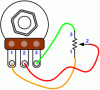
1st question - do I join the middle leg to one of the outer legs to make it 2-pin to match the original? I know I saw a picture posted by dlucy of that but I can't find it for the life of me.

2nd question - can I start with the new trim pot all the way to the left, turn on the receiver, and then turn it up with the multi meter hooked up until it reaches 25mV? or should it be close first?

3rd question - do people replace the output transistors? they are SC1030. They seem to be fine (tested with diode setting), but do they wear out and would there be a benefit to replacing it with a modern, higher-quality one?
 
1st question - do I join the middle leg to one of the outer legs to make it 2-pin to match the original? I know I saw a picture posted by dlucy of that but I can't find it for the life of me.

Don't feel bad; I had a hard time finding the photos, too.

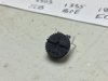
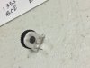
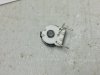
Yes, you short the middle pin of the trimpot (the wiper) to one of the two outer legs:

fig4_004.gif
IMG_0492.JPG
IMG_0494.JPG
IMG_0496.JPG
IMG_0498.JPG
IMG_0500.JPG


2nd question - can I start with the new trim pot all the way to the left, turn on the receiver, and then turn it up with the multi meter hooked up until it reaches 25mV? or should it be close first?

Set the new trimpot to the middle before powering up.

3rd question - do people replace the output transistors? they are SC1030. They seem to be fine (tested with diode setting), but do they wear out and would there be a benefit to replacing it with a modern, higher-quality one?

Transistors, in general, don't go bad over time. The 2SC458 is one of the rare exceptions. If you think the 2SC1030 output transistors you have are good, there is no compelling reason to replace them. You can replace them with something modern, if you want, but there is no compelling reason to do so. Modern devices will likely be lower noise and higher performance, but that should appeal only to us OCD people. When I've replaced output transistors (almost always because I'm nutty) I've gotten a small number of extra watts before clipping and a little lower THD. Your results will likely vary. If you really want higher watts and lower noise, you'd need to go deeper than just replacing the output transistors.

Whichever way you go, let us know.
 
Done for now!!! Huge thanks again Doug. I ended up keeping the original output transistors, they all checked out fine. The only thing that makes me want to replace them is it seems like they might not be made much longer...

I also replaced all the SC1344's on the tone board with the KSC1845's, and did the same with the SC458s on the main amp board (bias stabilizer). I ended up using the KSC1845's to replace the SC458s rather than the BSC550s. The BSC550's were about 100 higher hFE (428 vs 520-ish), but the 1845s were all testing exactly the same and came off a roll. Given my tester isn't fantastic, I reasoned the 1845s were more likely to be a closer match.

Installed the new bias pots and was able to dial it right in, so glad i went with those as the old ones looked rough. DC offset was still just under 20 on each side. On my someday list are the big 4700 caps, maybe output transistors. But it sounds great!!!! Might be in my head but the bass does seem better, and it just sounds the way I hoped it would. Absolutely love this amp.

Having done all this what I really want to do is a more through test to see what the specs are. More for curiosity, for now it sounds great and I'm enjoying it right now. Also looking for another amp, this was so much fun I want to try another one!!
 
Last edited:
You've... Got... TO-66 or TO-3 cans... Instead of TO-220 output... Transistors....

I've never seen that....

No, wait... You're working on a HK430 twin powered unit, not a 330c. I'm getting confused. Please start a new thread for your 430 restoration.
 
Ok, so I am getting 11mV on one channel and 65mV on the other channel for DC offset? Anyone else seen such difference? Is there a place to find matched transistor? I am guessing the offset is coming from Main Amp board as it is capacitor coupled from Pre. Which pair will likely be causing it? I am kicking myself for not measuring before making the mods. I changed 2SC458 with the suggested ones. Any help is greatly appreciated.
 
Does this receiver have an offset adjustment or no?

Most offsets are caused by a poorly matched differential pair or a bad input resistance mismatch on the input pair.
 
The 330C only has an idle adjustment, at VR401-402, on the main amp board. The adjustment procedure is on page 4 of the service manual.

65 mV isn't horrible, but do try to reign it in with the trimpot. If you cant, then start replacing transistors in matched pairs.

$20 component testers from eBay or Amazon are good enough for this kind of matching.
 
Back
Top Bottom