• The move to the new server is done. There are some software and database maintenance updates in process. This has us passing the hat around to help out. We appreciate any donations. Seriously, even a dollar helps. The payment page may be found here - https://www.audiokarma.org/support.html

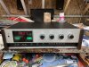
Recapping and restoring and upgrading a Heathkit AR-1515 receiver

I'll bite
First understand I built one with my father in the late 70s.
I picked up one for nostalgia sake. Then a second fell in my lap so I bought that one too.
Like many here I've spent a fair amount on gear over the years. So to frame the response. It's a very good receiver. I don't really listen to fm except in the car anymore so I'll keep my evaluation to the rest. The preamp section is top notch as good and better than some of the separates I've had. The amp section is good. IMO not as good as as the preamp. Overall I think it compares favorably with the receivers of its era. I won't bother to say it's as good as ..... or better than that. Everyone has their favorites and nobody has heard everything. I listen to Mac tube separates for the most part. I don't think I'm knocking it when I say it's not as good. It's not. The nostalgia wore off and after it sitting idle for over a year I sold it to someone (I think a contributor in this thread) who added feet, resprayed the top cover changed the lamps to leds and gave it more tlc than I was willing to. He seems thrilled with it and I'm happy it's being enjoyed and appreciated rather than gathering dust.
 
Yes, I was thrilled to buy it from njphoenix! Not only was it an AR-1515 but it was superbly rebuilt by dlucy. Picture below.4474FB27-AD79-48B8-A991-C0BEE70023F0.jpeg
My original AR-1515 will be 45 years old this year. It is a solid well built receiver that served me well in my stereo system into the late1990s until I bought my first AVR. Now I use it with a Sonos Connect to power a pair JBL L110s in the wife’s garage. The preamp power amp sections are very good. The FM section is not too shabby either. What is nice about Heathkits is being able to use the assembly manual to help diagnose problems and do the repairs yourself. Power wise it puts out 70 watts RMS per channel with less than .08% harmonic distortion. If you don’t need the tuner section find an AA-1515 integrated amp, you get the same preamp and power amp.

Larry
 
Last edited:
That reminds me, my first AA-29 (the little brother to the various -15 series Heathkits) I built, just turned 46 years old on March 18 (the day I completed it).

Doug.
 
FYI the answer to my August 2021 question, how warm do the heat sinks get on the dlucy rebuilt AR-1515, is that they run about 3-4 degrees above the ambient room temperature at a low volume.

Larry
 
Recently I purchased 16 MJ21196G transistors from Newark. I hFE matched 4 of them, which ranged from 48-52, with my DMM. I installed them in the Heathkit AA-1515, that I posted pictures of in this thread back in 2020, that the kit builder had used the very small gauge wire in the power supply. The MJ802 transistors that were replaced ran 15 to 20 or so degrees warmer than the ambient room temperature at a low volume level. They ranged in hFE from 15 to 83. Now the sound of the amplifier seems to have changed to being on the strident side. With the MJ802 transistors it had a warmer more listenable quality. It might just be my imagination. Anybody have any thoughts?

Larry
 
Last edited:
I know the discussion has been mostly technical/performance but the -1515 series appearance is most attractive, too.

Doug
 
Doug, I’ve always thought the same thing about the looks of the -1515 series, too, They always look good on or off.

Larry
 
Well, apparently it was my imagination or the transistors have now been broken in. I did another comparison listen between the amp with the new transistors and another one with the same source and speakers with volume levels matched and they sound essentially the same. I have been running the amp for 15-16 hours a day for the last 3 or 4 days at a low to moderate volume level for break in.

Larry
 
Part of my strident sound problem was with the Sonos volume control being too high on the Port and Connect that I use for my audio wi-fi. With the volume too high it apparently over drives the preamp stage in both the AA-1515 and the Carver CT17 that I use with the other system in my garage. I knew this was a problem but had forgotten about it. Listening to the AA-1515, with the new MJ21196G transistors, the bass or lower end still didn’t sound right. I guess you could say it has a very tight controlled sound, lacking warmth. I read up on damping factor. I suspected it might be possible that the new transistors had a much lower internal resistance which would increase the damping factor. The higher the damping factor the more control the amplifier has over the speakers. So I rigged up a pair of 2.5 ohm 20 watt resistors in series with the speakers and the amp. Low and behold the bass was fuller, not quite as sterile as it was before, but much more pleasant to the ear.
The AA-1515 and AR-1515 have a damping factor of greater than 60 with the OEM MJ802 transistors. I suppose I could try to measure the resistance of the amp with the MJ21196G transistors to compute the new damping factor.
So, which resistor(s) would I change on the CB to lower the damping factor?

Larry
 
Last edited:
After some thought on my above post, I have decided to ditch the MJ21196G transistors and obtain MJ802G transistors. The output amps in the AR-1515 and AA-1515 were designed around the MJ802, that is probably the reason why the MJ21196G transistors don’t make the amp sound right.

Larry
 
Recently I purchased another AR-1515 receiver from an eBay seller for recap rebuild project. The seller said in his description that it did not power on and the selector switch knob turned freely. When I got it out of the box, I checked the main power fuse, took the top and small bottom covers off and pulled the power supply board. I also blew out all the accumulated dust from the inside using an air compressor. The main fuse was good and I could see no leaking or bulging capacitors. The selector switch shaft coupler was missing (now wish I had looked for it at that time).
I installed a new coupler and powered it up. Two panel lamps came on. I connected a pair of speakers and a music source and got tunes from the speakers. It sounded just fine, the balance pot was a little noisy, but that’s an easy fix. The AM section worked, I was able to pick up the local AM station without an antenna when I touched the tuning capacitor screws.
The readout didn’t work properly. The display worked but the numbers on the readout would not change when the tuner was adjusted. The FM section didn’t seem to work at first. I wasn’t leaving it selected long enough for it to warm up enough for it to come on. Pushing in the squelch defeat button helps, too. No readout with FM either and no signal strength meter operation. With an FM antenna connected it was able to pick up quite a few stations. The regulated 5 voltage to the counter board was measured at about 4.75 volts. I found 3 spare counter boards from the donors I have on hand and selected one of them. Pulled the original board and found the metal selector shaft coupler between the foil side of the board and the inside panel. Probably why the counter board didn’t work. The replacement board cured the problem with the readout working properly now. Read up in the manual for the signal strength meter problem. Pointed to the AM FM IF board. I knew the meter worked on the AM side, so took a look at the schematic and saw that there is an 18k ohm resistor and a diode in circuit from the FM section just before leaving the board to the meter. The reason for the problem was the broken 18K resistor. I replaced the resistor/diode combo with another from a spare board and now the SS meter works. The power switch was sticking when it was pushed in to turn off, I shot it with some fader lube, and it works properly now. My plan is to do a complete recap and I may update the output amp, control, preamp and power supply boards with metal film resistors.

Larry
 
Doug (dlucy), where did you obtain the silicone sheets you used to replace paper insulation sheets in your rebuild?
I found a discrepancy in the CVS.text list, or at first I thought there was. I was checking my shopping cart list at Mouser to make sure I had all the resistors shown in the manual for the power supply and came across a 332 ohm resistor listed for a 330 ohm resistor that was not in the manual parts list. In both manuals I have R814 and R815 are 180 ohm resistors. I looked back at the picture of the power supply you posted earlier in the thread and it shows the 330 ohm resistors on the board. You had taken the pic with the board laying on the parts list page of the manual for the board and shown near the top of list was 330 ohm in place of the 180 ohm. Heathkit must have changed something in the circuitry to warrant the change. It would have dropped the voltage to close half of what it originally was.
Larry
 
!/4" coupler came from either Fastenal or Mcmaster-carr. Billwojo got them for us.
If you cant find ask him ( i think its a fairly common item.)
 
Doug (dlucy), where did you obtain the silicone sheets you used to replace paper insulation sheets in your rebuild?

I found a discrepancy in the CVS.text list, or at first I thought there was.

. . .

You had taken the pic with the board laying on the parts list page of the manual for the board and shown near the top of list was 330 ohm in place of the 180 ohm. Heathkit must have changed something in the circuitry to warrant the change. It would have dropped the voltage to close half of what it originally was.
Larry

the silicone sheets are kitchen ware from Amazon: big 18x14 sheet for kitchen counter or cookie sheet, cut down to size I needed.

yes, I don’t sdoubt there were some schematic-to-actual deviations like that. I make a list on a spreadsheet of the parts from part list, but then verify as I receive each component from the board. I’m betting it was something like that.
 
Thanks, Doug. I thought that’s what you might have done but wasn’t sure. The AR-1515 that I’m going to recap and update the resistors on five of circuit boards has the paper insulation but it is still thoroughly stuck to the panels. I may not update them, but if I decided to, I wanted to know where to get the sheets.
I’ve been slowly adding the necessary parts to my cart at Mouser. There are a few Nichicon capacitors that you used that aren’t available at this time, as you are probably well aware of. I have found replacements, just hope they will be as good as the Nichicons.

Larry
 
Hi all,

I'm just starting on a rebuild (recap) and clean of an AR-1515 since I finally have time off of work to work it. I have built other kits in the past. I just completed building a HealthKit Oscilloscope that was NIB I picked up off of ebay! Anyhow, I replaced the power transistors and also replaced the speaker connectors on the back since mine didn't have the plug in parts to make them work. The good news is it powers on, AM, FM, Loudness, bass, treble, balance, etc. all seem to work. I think 3 of the 4 power transistors (MJ802) were bad which is why I replaced all of them. Anyhow, I get sound (AM/FM) out of the right channel. The left Channel when a speaker is plugged in, I get loud hum. I get hum whether the small jumpers are plugged into the pre amp/amp to connect them on the back. My guess is I have an issue with the Left power amplifier. My question is, which side is the left amp. Is it on the left side if I'm facing the front or is it on the left side if I'm facing the rear? And if you have any ideas what to check for a loud hum (that is not controlled by the volume) that would be great. Any other tips would be appreciated as well.

Thanks,

Fred
 
Back
Top Bottom