FredGAR1515
New Member
Looks great!! I need to remount my big caps on that board...they are too tall and hits the chassis.



 View attachment 2775783 View attachment 2775782
I would like to recap the Pre Amp Board but I don't see any easy way to get it out without unsoldering a bunch of wires! Do you have any ideas of getting to the preamp board?Made a command decision not to update the resistors on the control and preamp boards. I replaced the electrolytic capacitors on the control and muting boards this afternoon.
Larry
nice work! Very clean!!View attachment 2775790 View attachment 2775791 View attachment 2775783 View attachment 2775782
I finished installing the output amp’s power supply capacitors and replaced all the capacitors and most of the resistors on one output amp board. There are two 15k ohm (one is a half watt and the other is a 1 watt) resistors on each of the output amp boards. Some time ago I had purchased 20 15K ohm 2 watt metal film resistors thinking they would work just fine, then I read somewhere that it’s best to replace them with the same wattage because they can work like a fuse in the circuit.
So now I waiting for the ones with the proper wattage.
Larry
Wow that is amazing! Can you get me the part number or the place you ordered these LEDs from? I would like to update mine. Was it just a straight swap?View attachment 2784996 I installed the LEDs in the display this morning. Boards left to do are the counter, AM/FM RF, AM/FM IF and the FM Multiplex.
Larry
When you say the "Drivers" on the readout board, what would that be? Which parts? And thanks for the tips on doing the preamp board. I never thought about doing it that way!! That will make it much easier!!Fred, thanks for the praise. i did the preamp board this morning. The input/output connectors can be unbolted (1/4” nuts) from the back panel to give you a little bit of playing room with the board. I also unbolted the board where it is attached to the chassis. Once the nut and screw are removed you can turn the board so the foil side is up. Moving the adjacent am/fm boards up makes it a little easier to access those nuts on the two input/output connector sections. I also took out the FM Dolby board. Can’t use it, no sense in keeping it in the receiver. There are 10 capacitors on that board.
I discovered on the output amp boards that I had used NP 10 uF 50V capacitors instead of the required 100V ones that are at the input. I put the proper ones on the board this afternoon. Had to pull the output transistors and heat sinks. I filed off the round tops of the LEDs that I will using for the panel lamps. Filing so they are flat disperses the light better.
Should you decide to do the control board, you will have remove the front panel, take the bottom panel off the power supply section and loosen the large one. I put the receiver on its left side since I am right handed. Most of the board is fairly easy to access. When removing the large knobs I mark them on the back side so they can easily be put back on their proper shaft. You shouldn’t have to remove the buttons on all the switches but you will have to pull the knobs off the three pots for balance, bass and treble. When I replaced the capacitors on it, I had a short section of the foil break off at one of the holes for one of the 5 uF capacitors. Left the lead of the new capacitor long, used heat shrink and soldered the lead to the end of the foil trace where the other component was soldered.
As far as the readout goes, I would suspect the drivers on the readout board. I’ve never had the problem you described. Most of the time it’s the counter board, and then the wrong numbers are displayed.
Larry
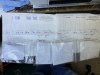
That is so cool! I built a few things Heathkit wise back in the day. I had a Heathkit H-8 Computer (purchsed used already built) but I built the H-19 CRT for the computer! Also built the clock and a touch sensitive on/off switch. I really wish I would have built so many other things. Oh I did buy off ebay a 4105 Oscilloscope unbuilt. That was fun to build! How many of the Heath Stereos did you build?Here’s a picture of my original invoices for my AR-1515, Audio Control Center and Equalizer.
View attachment 2785079
Thanks for the information. I will replace the cap for sure and check for corrosion. I'll pop the IC's off and plug them back in.I buy the LEDs from EvanDesigns.com.
I use their 5 mm universal LEDs, voltage is 7-19 volts AC/DC.
If you want the incandescent look order warm white or if you like the blue use the cool white.
You will need 12 if you’re going to do all of them. I usually ask them to pair up 2 of them to use for the FM lamp and center tune meter lamp. They have a built in bridge diode so you don’t have to worry about polarity. I use some putty to hold the LEDs in place since they are smaller in diameter than the original bulbs. The putty also blocks any light that may shine back into the receiver. The putty is fairly pliable, what I have is used for sealing a speaker in a cabinet. The LEDs ED uses have a round top, to disperse the light better, I file off the rounded top so it’s flat.
There are 3 integrated circuits on the readout board. You might have corrosion on the leads. Also check the plugs that connect to the counter board. If you have the 100 uF capacitor for the counter board, I would suggest you replace it. It‘s an easy peasy job.
Larry
See attached picture to let me know if this is what you got? What did you mean "ask them to pair up 2 of them"? I understand using 2 for those 2 displays. What brand of putty do you use? Only thing I can think of is plumbers putty. I watched the video and it looks like you attach the LEDs to the "Resistor, bridge rectifier, filtering capacitor", is that correct? They said you could connect up to 4 lights per bridge rectifier. IS that what you did?I buy the LEDs from EvanDesigns.com.
I use their 5 mm universal LEDs, voltage is 7-19 volts AC/DC.
If you want the incandescent look order warm white or if you like the blue use the cool white.
You will need 12 if you’re going to do all of them. I usually ask them to pair up 2 of them to use for the FM lamp and center tune meter lamp. They have a built in bridge diode so you don’t have to worry about polarity. I use some putty to hold the LEDs in place since they are smaller in diameter than the original bulbs. The putty also blocks any light that may shine back into the receiver. The putty is fairly pliable, what I have is used for sealing a speaker in a cabinet. The LEDs ED uses have a round top, to disperse the light better, I file off the rounded top so it’s flat.
There are 3 integrated circuits on the readout board. You might have corrosion on the leads. Also check the plugs that connect to the counter board. If you have the 100 uF capacitor for the counter board, I would suggest you replace it. It‘s an easy peasy job.
Larry
Picture attached now...lolSee attached picture to let me know if this is what you got? What did you mean "ask them to pair up 2 of them"? I understand using 2 for those 2 displays. What brand of putty do you use? Only thing I can think of is plumbers putty. I watched the video and it looks like you attach the LEDs to the "Resistor, bridge rectifier, filtering capacitor", is that correct? They said you could connect up to 4 lights per bridge rectifier. IS that what you did?
Thanks again for all your help!