• The move to the new server is done. There are some software and database maintenance updates in process. This has us passing the hat around to help out. We appreciate any donations. Seriously, even a dollar helps. The payment page may be found here - https://www.audiokarma.org/support.html

Recapping and restoring and upgrading a Heathkit AR-1515 receiver

Typically, Heathkits have the ,left channel output amplifier on the left as you face the front of the unit. However, I don't have a 1515 so other guys on here would know for sure.

Doug
 
As you face the receiver the left channel output amp is on the left side. Fred, do you have the manual with the schematic?

Larry
 
Fred, when you replaced the output transistors did you notice any burned resistors? Check to make sure the RCA phono plug is properly connected to the female input connector. The loud hum may be caused by a poorly connected ground wire to chassis ground from the output amp board. You may already know this, but use a 100 ohm 1 watt resistor to discharge both of the large output amp power supply capacitors before you connect or disconnect either of the output amp board wires or do anything with the that power supply if the receiver has been powered on and then powered off.

Larry
 
Last edited:
Fred, when you replaced the output transistors did you notice any burned resistors? Check to make sure The RCA phono plug is properly connected to the female input connector. The loud hum may be caused by a poorly connected ground wire to chassis ground from the output amp board. You may already know this, but use a 100 ohm 1 watt resistor to discharge both of the large output amp power supply capacitors before you connect or disconnect either of the output amp board wires or do anything with the that power supply if the receiver has been powered on and then powered off.

Larry
Thank you for the information. I have not taken anything apart. When I changed the transistors, I just took the covers off and unscrewed them and pulled them out thus didn't get a great look at the condition of the resistors. I was reading in the manual about that process you just described using the 100 ohm 1 watt resistor. I'll have to find that section again and read up on it. I'll have to see if I have a 100 ohm 1 watt resistor. And I understand what you mean about the female input connector as well as checking the ground.

Larry, I do have the full documentation. I will discharge everything before I pull off the output amp boards.

Again, thanks for the info and I'll provide an update when I get the output amp boards off. I will recap them at that time as well.

Thanks,

Fred
 
Larry, I was looking in the manual for the section on discharging the caps. On page 182 of the assembly manual, I think this is what you are talking about correct? In the manual, it says to use the 100 ohm 2 watt resistor. Will a 1 watt work ok?

Thanks,
Fred
 
Larry, I was looking in the manual for the section on discharging the caps. On page 182 of the assembly manual, I think this is what you are talking about correct? In the manual, it says to use the 100 ohm 2 watt resistor. Will a 1 watt work ok?

Thanks,
Fred

Fred, I was going by what I thought it was, sorry I didn’t have the manual handy when I replied. I would use what the manual recommends which would be the 2 watt. You should be able to find some inexpensive ones on ebay. In fact you can buy 5 for under 3 bucks with free shipping.
You can easily access the output amp power supply by removing the smaller bottom panel.
Fred, did you get any audio other than the loud
hum from the left channel?

Larry
 
Last edited:
Hi Larry,

No audio at all out of left channel. From right, full audio, base, treble, balance, loudness, all the controls worked. AM/FM both worked. And the volumn doesn't change the hum...its just hum!
 
Is the hum there regardless of what is selected? It’s not blowing the fuse or cooking anything on that board? You could have a bad capacitor on that board, too.

Larry
 
Last edited:
Yes, in the left channel, hum is always present regardless of what is selected. I disconnect the speaker and just have a speaker on the right channel, everything works fine. When just the left speaker is connected (no right speaker) it did pop the fuse but I only have a 1 amp slowblow fuse in right now to protect things. With just the right speaker, again it all works fine. I have a "recap" kit so plan to replace all the caps that it recommends. I am going to do the power supply and both power amp boards first. It doesn't appear to be cooking anything on any of the boards.

Thanks,

Fred
 
I am curious as to what you will find when you pull the board. If one or both of the MJ802 transistors go usually it’s from a direct short. There is a circuit on the board that is supposed to protect the output transistors when the output is shorted but only for a time. I learned the hard way back in the early 90s. The speaker wires attached to the left channel connector had frayed enough that they had shorted unbeknownst to me. When I would turn up the volume I would hear distortion, which wasn’t very often. I neglected to investigate and eventually had to replace both output transistors along with a few other components because they blew.

Larry
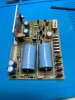
 
I am curious as to what you will find when you pull the board. If one or both of the MJ802 transistors go usually it’s from a direct short. There is a circuit on the board that is supposed to protect the output transistors when the output is shorted but only for a time. I learned the hard way back in the early 90s. The speaker wires attached to the left channel connector had frayed enough that they had shorted unbeknownst to me. When I would turn up the volume I would hear distortion, which wasn’t very often. I neglected to investigate and eventually had to replace both output transistors along with a few other components because they blew.

Larry
Thanks for the tips. I will be sure to look at all of that when I get it apart. I'll post updates here as I make progress and if I have more questions! I really appreciate the help. I'm assuming you have "recapped" an AR 1515 before. If so, any tips on taking boards out and disassembly tips?
 
Do one board at a time. Thoroughly check your work such as right capacitor in the right spot and that it’s in proper position as to polarity. Double check for unclipped soldered leads. I missed a lead on a power supply board with the rest of the boards all connected, not good.
I haven’t completely recapped an AR-1515 yet, but I’ve done the power supply boards and the output amp boards on three AR-1515s. I have plans to completely recap and replace all the resistors with metal film resistors on the power supply, output amp, control and preamp boards in an AR-1515 that I bought earlier this year.
I have four AA-1515s, an AR-29, two AA-29s and an AJ-1515 that I have completely recapped.

Larry
 
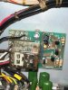
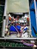
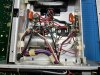
Hi, have the power supply, power supply board and muting board recapped. I also reapplied heat sink grease to the transistors on the power supply board. Came out pretty good. Working on the power amps next.
 

Attachments

  • AR-1515 - Power Supply Board Before.jpg
    AR-1515 - Power Supply Board Before.jpg
    97.6 KB · Views: 32
  • AR-1515 - Power Supply Board After.jpg
    AR-1515 - Power Supply Board After.jpg
    138.7 KB · Views: 28
  • AR-1515 - Muting Board After Recap.jpg
    AR-1515 - Muting Board After Recap.jpg
    131.6 KB · Views: 26
  • AR-1515 - Bottom New Caps.jpg
    AR-1515 - Bottom New Caps.jpg
    149.7 KB · Views: 25
  • AR-1515 Beginning Bottom.jpg
    AR-1515 Beginning Bottom.jpg
    143.5 KB · Views: 26
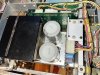
  • AR-1515 Beginning Top Big Caps.jpg
    AR-1515 Beginning Top Big Caps.jpg
    145.4 KB · Views: 28
  • AR-1515 Top Big Caps Installed.jpg
    AR-1515 Top Big Caps Installed.jpg
    138.7 KB · Views: 30
Fred, what are the values of the large power supply capacitors? I think you did mention that you had bought one of those capacitor package deals from the seller on ebay. From his pictures, they look to be 12,000 mF 50 V.

Still curious about what you will find out about the one output amp board.

Larry
 
Hi Larry,

I found a "sketchy" gound connection when I was recapping the power supply. Yes, what you have listed is what is in. The Caps I took out were 10,000 mF and 55wv. So I hope these being modern, will be ok since the voltage is 43 volts.

Regarding the hum, I took the boards out and tested all the "tests" from the manual. I also had a buddy that has all the test equipment, we hooked it up to a signal generator, power, etc. and it doesn't appear to be the board itself (if that makes sense). The sound that was generated seemed to be normal with no hum. So I hope the loose ground I found was the cause. When I get the power amps recapped, I'm going to try with the new power supply and power amp boards and see if it is fixed.

I'll be sure to post an update when I do that.
 
Howdy, Fred,
Sure happy to hear that your hum problem was a poor ground. Always nice when it’s something on the simple side. Looking forward to your updates.

Larry
 
Well, not sure the hum is gone. I need to put it back together and try it out. I haven't done that by fingers crossed that is it. I'll let you know.
 
Hi Larry and all,

Great news! The recap of the PS, and Power Amplifiers and the repair of 2 grounds have solved the Hum. The AR-1515 that didn't work when I purchased it, now works! I'm a happy camper! I have a few more boards to recap but that fact that everything works is awesome!

I am looking for a part that if you or anyone else that reads this could part with, please let me know. I need the coupler fitting that connects the selector for AM, FM, Tape, etc. The one I have was messed up and split into 2 pieces. I tried epoxy but no luck. I have zip ties holding it together but it's not working when it gets hot. So if you have a AR-1515 parts receiver, would be happy to buy and pay shipping.

And the sound is amazing in this Stereo! Such depth and spacious sound!
 
012689A9-6CB1-4912-9F9A-99E0EC0401FE.jpeg Fred, just buy an aluminum 1/4” shaft coupler off of eBay. They are much better than the original rinky dink ones Heathkit used.
I just spent part of the afternoon replacing all the resistors and capacitors on the power supply board in the AR-1515 that I acquired last year. I also replaced the 6000 uF 15 volt capacitor that’s part of the 5 volt power supply at the bottom of the power supply section. I will be replacing the large filter caps next.
Happy to hear the other channel hum problem was a simple fix and that you enjoy how it sounds. Those poor ground connections in the power supply obviously were the source of the hum.

Larry
 
Last edited:
Back
Top Bottom