Hi,
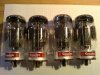
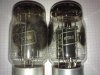
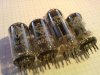
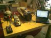
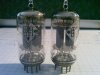
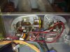
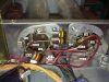
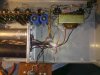
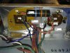
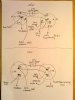
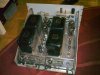
I recently got a pair of McIntosh MC75 monoblock amplifiers that I want to give an overhaul. The two units were used in a shaker table amplifier which was stored in a garage for some decades. The tubes were dusty (still are) but seem to be stock and in good shape. I even found the second shielding can that's missing in the pictures.
Most of the info I got from the helpful people over at diyaudio, where I started this thread: http://www.diyaudio.com/forums/tubes-valves/163204-pleas-help-identify-mcintosh-valve-amplifier.html .
So why another thread here? Looking for anything related to the MC75 or similar units I stumbled upon this forum and it's McIntosh subsection. And after reading a lot invaluable info I hope to get some input on my specific project. I'll post step-by-step pictures (like http://audiokarma.org/forums/showthread.php?t=69835&highlight=mc240 ) if there's interest.
In the meantime I've figured out how to proceed with the amplifiers. The part selection is going to be reasonably modern, but conserving the looks of the amp. Not being used to carbon resistors (solid state background with matched 1% metal film resistors and high power MOX...) I initially wanted to toss them all but got convinced to keep a few in places where they might actually be the better choice.
After reading http://www.audiokarma.org/forums/showpost.php?p=1171856&postcount=93 I also decided not to keep any of the original carbon resistors but to replace them with new ones.
Replacing all electrolytic capacitors seems logic, but after reading
http://www.audiokarma.org/forums/showpost.php?p=1752684&postcount=130
http://www.audiokarma.org/forums/showpost.php?p=3442681&postcount=361
http://www.audiokarma.org/forums/showpost.php?p=1509868&postcount=119
I decided to also replace all of the other caps, except for the Black Beauty caps of the 2nd stage.
Other parts will also be replaced, like the thermistor and the diodes. More on that later.
So here's the plan:
Electrolytic capacitors:
250uF250V PSU with minus ground (C13)
250uF250V PSU with minus hot (C14, black isolation)
Replacement: Auhenticap KTL3, isolated can. Direct replacement.
Source: http://www.die-wuestens.de/k8.htm
100uF500V/30uF450V PSU, twice (C15AB, C16AB)
Replacement: Auhenticap KTL9. This cap has four 50uF500V sections. I intend to use one single 50uF500V and the three others in parallel to form a 150uF500V.
Source: http://www.die-wuestens.de/k8.htm
12uF250V bias, axial (C12)
12uF250V cathode KT88, axial (C9, C10)
Replacement: Sprague Atom. Maybe 20uF500V but I'm not sure if the actual voltage that will be presented to the cap won't be too low to keep up the oxide layer. Or maybe I'm just paranoid.
Source: Recommend me one.
100uF3V cathode 12AX7, axial (C3)
Replacement: Not sure yet, but will be axial part. Maybe a Sprague Atom 100uF50V.
Source: ?
Film caps:
0.47uF200V input (C1)
0.047uF600V 1st coupling (C5, C6)
0.22uF400V 2nd coupling (C7, C8)
0.22uF400V grid 12AU7 (C4)
0.01uF600V PSU (C11, C12)
0.1uF200V output socket (C19)
Replacement: All bumble bees (all caps except C7 and C8) will be replaced. I want to use the original values even though it seems a bit weird taking the tolerances into account...for electrolytic caps I don't mind tweaking the numbers.
I'd prefer Black Beauty 160p for C1, C5, C6 and C4. C11, C12 and C19 I don't know yet. But they should blend in with the other choices.
Source: eBay, ?
Then there's two additional caps:
100pF?V at the anode of the 12AU7 (C18). I can't figure out what type that is. Voltage rating should be around 400V methinks.
330pF?V at the cathode of the 12AX7. I'm not even sure this cap is installed...supposed to be “tubular ceramic”.
Replacement: Not even sure if necessary.
Source: ?
Resistors:
(Label, Value, Location; Replacement)
R1 220k Input, 5%; RN65 Metal Film
R2 100k Input, 5%; RN65 Metal Film
R3 250k gain pot, switch, stays
R4 22k grid 12AX7
R5 2.7k cathode 12AX7, 5%; RN65 Metal Film, match other channel
R6 3.3k cathode 12AX7
R7 68R cathode 12AX7, 5%; RN65 Metal Film, match other channel
R8 100k anode 12AX7
R9 2.2M grid 12AU7; RN65 Metal Film
R10 18k 1W cathode 12AU7, 1W
R11 27k anode 12AU7, 5%
R12 30k anode 12AU7, 5%
R13 2.2M grid 12BH7, 5% high voltage drop!
R14 2.2M grid 12BH7, 5% high voltage drop!
R15 220k grid 12BH7, 5%; RN65 Metal Film
R16 220k grid 12BH7, 5%; RN65 Metal Film
R17 2.7k 1W cathode 12BH7, 1W
R18 12k 2W anode 12BH7, 2W, matched 1% to R21; non-inductive WW
R19 1M grid 12BH7; RN65 Metal Film
R20 1M grid 12BH7; RN65 Metal Film
R21 12k 2W anode 12BH7, 2W, matched 1% to R18; non-inductive WW
R22 18k cathode 12BH7
R23 18k 1W cathode 12BH7, 1W
R24 18k 1W cathode 12BH7, 1W
R25 18k cathode 12BH7
R26 220R 5W grid KT88, wirewound 220R, 5W; act as fuse, must fail open, 5W maximum! See link below.
R27 220R 5W grid KT89, wirewound 220R, 5W; http://www.audiokarma.org/forums/showpost.php?p=2900298&postcount=8
R28 Thermistor PSU, 79R cold, <0.7R hot; CL80 http://www.audiokarma.org/forums/showpost.php?p=432963&postcount=3
R29 10k 2W PSU; MOX 2W
R30 100k 1W PSU; MOX 1W
R31 100k 1W PSU; MOX 1W
R32 100k PSU, 5%; MOX 1W
R33 62k PSU, 5%; MOX 1W
Where no replacement is specified I will use carbon resistors. KOA-Speer Carbon Film have been recommended to me. About the higher power ones I'm not sure yet. Any opinions?
The WW resistors could be WW Mills MRA-12. Opinions?
The thermistor will most likely be replaced by a CL80 thermistor. It has a cold (77°F or 25°C) value of 47Ohm and the maximum steady state RMS current is 3A. As the MC75 will draw 240W at 75W output, the current through the thermistor will be around 2A. The CL80 will have a residual resistance of 0.71Ohm at 75% of it's rated maximum current so it should be a good replacement.
Diodes:
SR1, SR2, 600V500mA, PSU
Replacement: UF5408
SR3, 400V65mA, PSU, Selenium
Replacement: UF4007 plus a dropping resistor to restore the -150V across C17. Anyone knows a good starting value for the MC75? I have no idea, 5k for starters?
I also want to connect te amplifier's chassis/circuit ground to earth-ground (or safey earth). The solder lug next to the output strip semms to be a good place, don't it?
Well, that'd be it, that's all I know for now. What do you think? What parts would you choose? And why?
Btw, I'm from Austria and we have 240VAC50Hz mains. But that is taken care of since I have a 4000VA isolation transformer with a 115V28A secondary...lucky me.
I recently got a pair of McIntosh MC75 monoblock amplifiers that I want to give an overhaul. The two units were used in a shaker table amplifier which was stored in a garage for some decades. The tubes were dusty (still are) but seem to be stock and in good shape. I even found the second shielding can that's missing in the pictures.
Most of the info I got from the helpful people over at diyaudio, where I started this thread: http://www.diyaudio.com/forums/tubes-valves/163204-pleas-help-identify-mcintosh-valve-amplifier.html .
So why another thread here? Looking for anything related to the MC75 or similar units I stumbled upon this forum and it's McIntosh subsection. And after reading a lot invaluable info I hope to get some input on my specific project. I'll post step-by-step pictures (like http://audiokarma.org/forums/showthread.php?t=69835&highlight=mc240 ) if there's interest.
In the meantime I've figured out how to proceed with the amplifiers. The part selection is going to be reasonably modern, but conserving the looks of the amp. Not being used to carbon resistors (solid state background with matched 1% metal film resistors and high power MOX...) I initially wanted to toss them all but got convinced to keep a few in places where they might actually be the better choice.
After reading http://www.audiokarma.org/forums/showpost.php?p=1171856&postcount=93 I also decided not to keep any of the original carbon resistors but to replace them with new ones.
Replacing all electrolytic capacitors seems logic, but after reading
http://www.audiokarma.org/forums/showpost.php?p=1752684&postcount=130
http://www.audiokarma.org/forums/showpost.php?p=3442681&postcount=361
http://www.audiokarma.org/forums/showpost.php?p=1509868&postcount=119
I decided to also replace all of the other caps, except for the Black Beauty caps of the 2nd stage.
Other parts will also be replaced, like the thermistor and the diodes. More on that later.
So here's the plan:
Electrolytic capacitors:
250uF250V PSU with minus ground (C13)
250uF250V PSU with minus hot (C14, black isolation)
Replacement: Auhenticap KTL3, isolated can. Direct replacement.
Source: http://www.die-wuestens.de/k8.htm
100uF500V/30uF450V PSU, twice (C15AB, C16AB)
Replacement: Auhenticap KTL9. This cap has four 50uF500V sections. I intend to use one single 50uF500V and the three others in parallel to form a 150uF500V.
Source: http://www.die-wuestens.de/k8.htm
12uF250V bias, axial (C12)
12uF250V cathode KT88, axial (C9, C10)
Replacement: Sprague Atom. Maybe 20uF500V but I'm not sure if the actual voltage that will be presented to the cap won't be too low to keep up the oxide layer. Or maybe I'm just paranoid.
Source: Recommend me one.
100uF3V cathode 12AX7, axial (C3)
Replacement: Not sure yet, but will be axial part. Maybe a Sprague Atom 100uF50V.
Source: ?
Film caps:
0.47uF200V input (C1)
0.047uF600V 1st coupling (C5, C6)
0.22uF400V 2nd coupling (C7, C8)
0.22uF400V grid 12AU7 (C4)
0.01uF600V PSU (C11, C12)
0.1uF200V output socket (C19)
Replacement: All bumble bees (all caps except C7 and C8) will be replaced. I want to use the original values even though it seems a bit weird taking the tolerances into account...for electrolytic caps I don't mind tweaking the numbers.
I'd prefer Black Beauty 160p for C1, C5, C6 and C4. C11, C12 and C19 I don't know yet. But they should blend in with the other choices.
Source: eBay, ?
Then there's two additional caps:
100pF?V at the anode of the 12AU7 (C18). I can't figure out what type that is. Voltage rating should be around 400V methinks.
330pF?V at the cathode of the 12AX7. I'm not even sure this cap is installed...supposed to be “tubular ceramic”.
Replacement: Not even sure if necessary.
Source: ?
Resistors:
(Label, Value, Location; Replacement)
R1 220k Input, 5%; RN65 Metal Film
R2 100k Input, 5%; RN65 Metal Film
R3 250k gain pot, switch, stays
R4 22k grid 12AX7
R5 2.7k cathode 12AX7, 5%; RN65 Metal Film, match other channel
R6 3.3k cathode 12AX7
R7 68R cathode 12AX7, 5%; RN65 Metal Film, match other channel
R8 100k anode 12AX7
R9 2.2M grid 12AU7; RN65 Metal Film
R10 18k 1W cathode 12AU7, 1W
R11 27k anode 12AU7, 5%
R12 30k anode 12AU7, 5%
R13 2.2M grid 12BH7, 5% high voltage drop!
R14 2.2M grid 12BH7, 5% high voltage drop!
R15 220k grid 12BH7, 5%; RN65 Metal Film
R16 220k grid 12BH7, 5%; RN65 Metal Film
R17 2.7k 1W cathode 12BH7, 1W
R18 12k 2W anode 12BH7, 2W, matched 1% to R21; non-inductive WW
R19 1M grid 12BH7; RN65 Metal Film
R20 1M grid 12BH7; RN65 Metal Film
R21 12k 2W anode 12BH7, 2W, matched 1% to R18; non-inductive WW
R22 18k cathode 12BH7
R23 18k 1W cathode 12BH7, 1W
R24 18k 1W cathode 12BH7, 1W
R25 18k cathode 12BH7
R26 220R 5W grid KT88, wirewound 220R, 5W; act as fuse, must fail open, 5W maximum! See link below.
R27 220R 5W grid KT89, wirewound 220R, 5W; http://www.audiokarma.org/forums/showpost.php?p=2900298&postcount=8
R28 Thermistor PSU, 79R cold, <0.7R hot; CL80 http://www.audiokarma.org/forums/showpost.php?p=432963&postcount=3
R29 10k 2W PSU; MOX 2W
R30 100k 1W PSU; MOX 1W
R31 100k 1W PSU; MOX 1W
R32 100k PSU, 5%; MOX 1W
R33 62k PSU, 5%; MOX 1W
Where no replacement is specified I will use carbon resistors. KOA-Speer Carbon Film have been recommended to me. About the higher power ones I'm not sure yet. Any opinions?
The WW resistors could be WW Mills MRA-12. Opinions?
The thermistor will most likely be replaced by a CL80 thermistor. It has a cold (77°F or 25°C) value of 47Ohm and the maximum steady state RMS current is 3A. As the MC75 will draw 240W at 75W output, the current through the thermistor will be around 2A. The CL80 will have a residual resistance of 0.71Ohm at 75% of it's rated maximum current so it should be a good replacement.
Diodes:
SR1, SR2, 600V500mA, PSU
Replacement: UF5408
SR3, 400V65mA, PSU, Selenium
Replacement: UF4007 plus a dropping resistor to restore the -150V across C17. Anyone knows a good starting value for the MC75? I have no idea, 5k for starters?
I also want to connect te amplifier's chassis/circuit ground to earth-ground (or safey earth). The solder lug next to the output strip semms to be a good place, don't it?
Well, that'd be it, that's all I know for now. What do you think? What parts would you choose? And why?
Btw, I'm from Austria and we have 240VAC50Hz mains. But that is taken care of since I have a 4000VA isolation transformer with a 115V28A secondary...lucky me.
Attachments

Last edited: