

You are using an out of date browser. It may not display this or other websites correctly.
You should upgrade or use an alternative browser.
You should upgrade or use an alternative browser.
Refurbishing two MC75 Monoblock Amplifiers
- Thread starter Rodeodave
- Start date


dshoaf
That high voltage buzz
Yep, very similar to the reconstruction of the ones I did. Nice documentation, too. I'm not sure everyone does it that way but certainly helps when the thing is taken apart and you have to stop for a few days for some reason.
On the cap clamps, I removed both of the sheet metal pieces that have the caps installed on them. They're easy to pop out once you've disconnected the wires. Then I used a cold-steel nail punch and a socket of the correct size to drift-out the pop rivets. This kept the sheet metal from being bent and not having any metal filings from trying to drill them out. Works great.
Next, when installing the capacitors in the clamps. Put a few turns of electricians tape onto the new caps to add a bit more insulation in case there are any small burrs on the clamps that might punch through the insulation on the cap bodies. The caps should fit snug in the clamp but you don't have to crank down on them, either.
Lastly, swap out the thermistors, too, as they are likely to break after so many decades. They'll be brittle.
Cheers,
David
On the cap clamps, I removed both of the sheet metal pieces that have the caps installed on them. They're easy to pop out once you've disconnected the wires. Then I used a cold-steel nail punch and a socket of the correct size to drift-out the pop rivets. This kept the sheet metal from being bent and not having any metal filings from trying to drill them out. Works great.
Next, when installing the capacitors in the clamps. Put a few turns of electricians tape onto the new caps to add a bit more insulation in case there are any small burrs on the clamps that might punch through the insulation on the cap bodies. The caps should fit snug in the clamp but you don't have to crank down on them, either.
Lastly, swap out the thermistors, too, as they are likely to break after so many decades. They'll be brittle.
Cheers,
David
Hi guys, thanks for the feedback.
I have decided to keep the Sprague 160p caps (0.22uF 600V, 2nd stage coupling, C7, C8) for now, and to replace all of the others with Orange Drop 716p in the signal path and Illinois Capacitor (C-U series) and Mallory (150s) for bypass caps.
In the meantime I removed the caps from the PSU. To drive out the rivets with a nail and a socket is a very clever idea. That'll be next.
I was already thinking about adding some rings of heatshrinking tube to the caps to have a tougher isolating material between the clamps and the capacitors' cans. Thanks for pointing this out, David, that's something that may be easily overlooked and could lead to catastrophic failure.
For now I'll leave all but the PSU resistors unchanged, and depending on the actual operating voltages I'll change a few. We'll see.
For the PSU I'm thinking of using Welwyn MFP2 resistors, these are 5%, metal film, 2W, 50ppm TC and pure copper leads. They are rated for 350V, so they would be fine (highest drop in PSU is 170V). An alternative would be the Vishay PR03 series, also 5%, metal film, copper leads, but rated 3W, 250ppm TC and 750V.
For a replacement of the thermistors i have a CL-80 type in mind, unless someone has a better idea.
So long,
Dave
I have decided to keep the Sprague 160p caps (0.22uF 600V, 2nd stage coupling, C7, C8) for now, and to replace all of the others with Orange Drop 716p in the signal path and Illinois Capacitor (C-U series) and Mallory (150s) for bypass caps.
In the meantime I removed the caps from the PSU. To drive out the rivets with a nail and a socket is a very clever idea. That'll be next.
I was already thinking about adding some rings of heatshrinking tube to the caps to have a tougher isolating material between the clamps and the capacitors' cans. Thanks for pointing this out, David, that's something that may be easily overlooked and could lead to catastrophic failure.
For now I'll leave all but the PSU resistors unchanged, and depending on the actual operating voltages I'll change a few. We'll see.
For the PSU I'm thinking of using Welwyn MFP2 resistors, these are 5%, metal film, 2W, 50ppm TC and pure copper leads. They are rated for 350V, so they would be fine (highest drop in PSU is 170V). An alternative would be the Vishay PR03 series, also 5%, metal film, copper leads, but rated 3W, 250ppm TC and 750V.
For a replacement of the thermistors i have a CL-80 type in mind, unless someone has a better idea.
So long,
Dave
Attachments

dshoaf
That high voltage buzz
On the thermistor, here's a good data sheet including theory to calculate what you'll need. IIRC, I've used CL-90s in the past.
Yep, your pics bring back memories, for sure. On the drifting out of the rivets, select a socket that is just slightly larger than the rivet head. Mount the metal support on the socket which is on its back face up. Then apply the nail punch, which should have the point of the shaft slightly smaller than the shank of the rivet. The rivet will pop right out after one blow of the hammer or BFBPH (big f$$king ball peen hammer).
One other thing, those 2 blue caps you've already mounted: Are you going to be able to get the cap mounts back in place without interference?
Cheers,
David
Yep, your pics bring back memories, for sure. On the drifting out of the rivets, select a socket that is just slightly larger than the rivet head. Mount the metal support on the socket which is on its back face up. Then apply the nail punch, which should have the point of the shaft slightly smaller than the shank of the rivet. The rivet will pop right out after one blow of the hammer or BFBPH (big f$$king ball peen hammer).
One other thing, those 2 blue caps you've already mounted: Are you going to be able to get the cap mounts back in place without interference?
Cheers,
David
Guten Abend zusammen! I made quite some progress since last time, so here's a quick roundup with plenty of pictures 
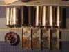
Driving out the rivets really was quite easy. Since I don't own a hammer (no kidding, my walls are reinforced concrete, don't even think about driving a nail in there) I had to use one of my dumbbells, and instead of the socket I used a wooden board with a hole in it. The ones that originally held the clamps for the diodes I drilled out to safe the somewhat brittle pertinax board from being damaged.
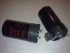
Before mounting the caps int the clamps I added a layer of thick heatshrinking tube to reinforce the isolation.
A comparison of the old vs. the new caps suggests that electrolytic capacitors' capacitance per volume sure increased in the last couple of decades.
The smaller axial type capacitors are the F&T 22uF 350VDC caps for the bias supply.
Driving out the rivets really was quite easy. Since I don't own a hammer (no kidding, my walls are reinforced concrete, don't even think about driving a nail in there) I had to use one of my dumbbells, and instead of the socket I used a wooden board with a hole in it. The ones that originally held the clamps for the diodes I drilled out to safe the somewhat brittle pertinax board from being damaged.
Before mounting the caps int the clamps I added a layer of thick heatshrinking tube to reinforce the isolation.
A comparison of the old vs. the new caps suggests that electrolytic capacitors' capacitance per volume sure increased in the last couple of decades.
The smaller axial type capacitors are the F&T 22uF 350VDC caps for the bias supply.
Attachments

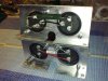
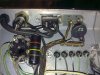
It then was time to rebuild the rectifier/bypass/bias supply board. The diodes got replaced by two UF5408 and the selenium rectifier got replaced by a single UF4007 and a 10k resistor in series with it. I hope the value works, otherwise I'll adjust it accordingly.
By rerouting some wires and sharing one pair of solder turrets for the diode/bypass cap, I could install the bias supply's diode and resistor without further hassle. Nice.
I then installed the new voltage doubler and the HT-supply according to the schematics I posted earlier. The cap in the voltage doubler is a Mallory 150 with 0.01uF and 630VDC. The HT-supply's first resistor is a Vishay Sfernice 10k 8W 5% 500V 75ppm metal film resistor. The 8W version has an acceptable size and can withstand 500V, which is not standard for MF. The others are the Welwyn MF2 mentioned in another post.
Oh, and I also installed the new CL80 thermistor.
I'd love to fire them up right away, but there's one thing I've learned: "Before you fire up the amplifier, check everything twice (once in the evening, once in the morning)..." (Nelson Pass, in http://www.firstwatt.com/pdf/art_zv8.pdf). And since it's 1am here I'll call it a day and head off to bed. More hopefully tomorrow.
By rerouting some wires and sharing one pair of solder turrets for the diode/bypass cap, I could install the bias supply's diode and resistor without further hassle. Nice.
I then installed the new voltage doubler and the HT-supply according to the schematics I posted earlier. The cap in the voltage doubler is a Mallory 150 with 0.01uF and 630VDC. The HT-supply's first resistor is a Vishay Sfernice 10k 8W 5% 500V 75ppm metal film resistor. The 8W version has an acceptable size and can withstand 500V, which is not standard for MF. The others are the Welwyn MF2 mentioned in another post.
Oh, and I also installed the new CL80 thermistor.
I'd love to fire them up right away, but there's one thing I've learned: "Before you fire up the amplifier, check everything twice (once in the evening, once in the morning)..." (Nelson Pass, in http://www.firstwatt.com/pdf/art_zv8.pdf). And since it's 1am here I'll call it a day and head off to bed. More hopefully tomorrow.
Attachments
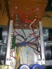
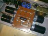
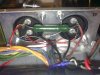
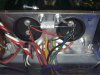

Oh yeah, they're up and running, both of them! 
I slowly brought them up with a variac, checking current draw, plate voltage and bias voltage. After a few iterations I ended up using 280R in series with the new UF4007 to get the bias voltage to -150VDC (same for both amps, MRS25 250V 50ppm 1% MF resistor). At the time of this adjusting process the plate was always set to 460VDC using the variac. The amp's voltage selector switch was set to 125VAC, the variac delivered around 121VAC for this configuration (460VDC plates and -150VDC bias).
I later checked all the voltage levels, and quite curiously the plate voltage dropped to 450VDC whilst the bias voltage stayed at -150VDC. Cranking up the variac to reach 460VDC plate voltage now leads to -153VDC bias voltage. I don't know how that happened.
The measurements were taken with a load at the output and the input was fully attenuated and shorted. I was using the same DMM for all measurements.
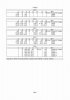
Please see the attached table for the values. Not too bad I'd say, after all those years in storage. The volume pot ('gain control') works flawlessly and without scratching.
The first song the amps played after all those decades was Johnny Cash 'Cry, Cry, Cry' in mono, through cheapish Sony 6 Ohm three-way speakers (connected to the 4 Ohm tap). Later I hooked them up to the annoyingly humming isolation step down transformer, finally listening to stereo. Even through the cheap speakers the sound was full and very pleasing, with surprisingly good imaging. Once they've earned my trust I'll hook them up to my horns. Now if there only was a cure for that humming transformer...
I slowly brought them up with a variac, checking current draw, plate voltage and bias voltage. After a few iterations I ended up using 280R in series with the new UF4007 to get the bias voltage to -150VDC (same for both amps, MRS25 250V 50ppm 1% MF resistor). At the time of this adjusting process the plate was always set to 460VDC using the variac. The amp's voltage selector switch was set to 125VAC, the variac delivered around 121VAC for this configuration (460VDC plates and -150VDC bias).
I later checked all the voltage levels, and quite curiously the plate voltage dropped to 450VDC whilst the bias voltage stayed at -150VDC. Cranking up the variac to reach 460VDC plate voltage now leads to -153VDC bias voltage. I don't know how that happened.
The measurements were taken with a load at the output and the input was fully attenuated and shorted. I was using the same DMM for all measurements.
Please see the attached table for the values. Not too bad I'd say, after all those years in storage. The volume pot ('gain control') works flawlessly and without scratching.
The first song the amps played after all those decades was Johnny Cash 'Cry, Cry, Cry' in mono, through cheapish Sony 6 Ohm three-way speakers (connected to the 4 Ohm tap). Later I hooked them up to the annoyingly humming isolation step down transformer, finally listening to stereo. Even through the cheap speakers the sound was full and very pleasing, with surprisingly good imaging. Once they've earned my trust I'll hook them up to my horns. Now if there only was a cure for that humming transformer...
Attachments


Nicely done!
You're a brave man testing those amps with Gold Lions!
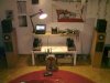
Here are Dave's former amps running the high end of a pair of big Infinity's.

From what I've been able to gather, after the rebuild, the sound is most affected by the 12AX7 and 12AU7 tubes, less so by the 12BH7, and lastly by the KT 88/6550 tubes.
Happy listening!
You're a brave man testing those amps with Gold Lions!
Here are Dave's former amps running the high end of a pair of big Infinity's.
From what I've been able to gather, after the rebuild, the sound is most affected by the 12AX7 and 12AU7 tubes, less so by the 12BH7, and lastly by the KT 88/6550 tubes.
Happy listening!
dshoaf
That high voltage buzz
I'm with AA about the Gold Lions. I'd suggest you lay hands on a set of EH KT-88s. They have been pretty hardy tubes and is what I used with the MC-75s above to get them started.
I burned the amps in for a number of months and kept monthly measurements of the operating voltages. Each month I would set the variac up so that plate voltages on the output tubes were exactly as called for in the schematic. Then, with a spreadsheet, I took measurements of all the tube pins where there's a voltage called for. This allowed me to quickly see if there was any stage drifting off for any reason. IIRC, these MC-75s didn't require any resistor changes due to drifting but the MC-30s I redid prior to the '75s required over 50% replacement of resistors due to drifting out of spec.
Cheers,
David
I burned the amps in for a number of months and kept monthly measurements of the operating voltages. Each month I would set the variac up so that plate voltages on the output tubes were exactly as called for in the schematic. Then, with a spreadsheet, I took measurements of all the tube pins where there's a voltage called for. This allowed me to quickly see if there was any stage drifting off for any reason. IIRC, these MC-75s didn't require any resistor changes due to drifting but the MC-30s I redid prior to the '75s required over 50% replacement of resistors due to drifting out of spec.
Cheers,
David
David and AA, you're both right, it is rather reckless to run the amps with the Genalex tubes, at least until I know they're safe. Using a quad of EH KT88 seems more reasonable.
I was able to greatly reduce the step down transformer's hum by placing the heavy beast on four rubber feet, as opposed to having it sit on wooden boards on the hardwood floor. The formerly stiff coupling led to a loud hum, now it's almost inaudible. Once I put it in a case it'll be totally gone, hopefully.
One thing that is bothering me though is that the MC75s' power transformers are getting somehow warm (still below 50°C/122F I'd guess) and, more worrying, they are humming audibly. When touching the transformer's cover the vibrations can be felt with the fingertips. That's not normal, is it?
The step down transformer puts out a steady 122VAC with 50Hz. I highly doubt that there is any DC present to saturate the cores. What else could it be?
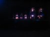
I found the time to take a long exposure shot of one of the amps. :drool:
I was able to greatly reduce the step down transformer's hum by placing the heavy beast on four rubber feet, as opposed to having it sit on wooden boards on the hardwood floor. The formerly stiff coupling led to a loud hum, now it's almost inaudible. Once I put it in a case it'll be totally gone, hopefully.
One thing that is bothering me though is that the MC75s' power transformers are getting somehow warm (still below 50°C/122F I'd guess) and, more worrying, they are humming audibly. When touching the transformer's cover the vibrations can be felt with the fingertips. That's not normal, is it?
The step down transformer puts out a steady 122VAC with 50Hz. I highly doubt that there is any DC present to saturate the cores. What else could it be?
I found the time to take a long exposure shot of one of the amps. :drool:
Attachments

Oh yeah, they're up and running, both of them!
I slowly brought them up with a variac, checking current draw, plate voltage and bias voltage. After a few iterations I ended up using 280R in series with the new UF4007 to get the bias voltage to -150VDC (same for both amps, MRS25 250V 50ppm 1% MF resistor). At the time of this adjusting process the plate was always set to 460VDC using the variac. The amp's voltage selector switch was set to 125VAC, the variac delivered around 121VAC for this configuration (460VDC plates and -150VDC bias).
I later checked all the voltage levels, and quite curiously the plate voltage dropped to 450VDC whilst the bias voltage stayed at -150VDC. Cranking up the variac to reach 460VDC plate voltage now leads to -153VDC bias voltage. I don't know how that happened.
The measurements were taken with a load at the output and the input was fully attenuated and shorted. I was using the same DMM for all measurements.
Please see the attached table for the values. Not too bad I'd say, after all those years in storage. The volume pot ('gain control') works flawlessly and without scratching.
The first song the amps played after all those decades was Johnny Cash 'Cry, Cry, Cry' in mono, through cheapish Sony 6 Ohm three-way speakers (connected to the 4 Ohm tap). Later I hooked them up to the annoyingly humming isolation step down transformer, finally listening to stereo. Even through the cheap speakers the sound was full and very pleasing, with surprisingly good imaging. Once they've earned my trust I'll hook them up to my horns. Now if there only was a cure for that humming transformer...
if you repalced seleniun rectifier you will need resistor in series. Voltage drop on selenium rectifier about 3 v. Silicon .5 v.
I know, that what the post says. I replaced the old selenium rectifier with a UF4007 and a resistor in series. Currently it's 280 Ohms, and I think the value a tiny bit too low since the bias ends up at -153VDC when the plate is set to 460VDC. Here's a picture of the new bias supply, small diode and resistor in the middle, followed by the 22uF cap: http://www.audiokarma.org/forums/attachment.php?attachmentid=242126&d=1290815601.
I noticed a slight hum that I believe could stem from the new silicone diode, maybe I'll try a 10nF foil cap across the UF4007 next time I'm in there and see if it helps. There was a lengthy discussion on selenium rectifiers in the tube audio section some time ago.
I noticed a slight hum that I believe could stem from the new silicone diode, maybe I'll try a 10nF foil cap across the UF4007 next time I'm in there and see if it helps. There was a lengthy discussion on selenium rectifiers in the tube audio section some time ago.
Last edited:
dshoaf
That high voltage buzz
Normal procedure for checking bias voltage is to use a variac, adjust line voltage so that you read +460 on the plates of the output tubes. Then, check the output tube grids for -58v with the +460 on the plates.
To adjust, first confirm that the 2 resistors R32/33 are within spec first. That ratio is critical. Next I insert a resistor decade box and adjust for -58 volts on the grids while readjusting line voltage for +460 on the plates of the output tubes. All this should be done after the amp is warmed up for 15 minutes or so.
As for the transformer hum, doubtful that there's a major problem unless overheating is observed.
How have they been sounding since your restoration?
Cheers,
David
To adjust, first confirm that the 2 resistors R32/33 are within spec first. That ratio is critical. Next I insert a resistor decade box and adjust for -58 volts on the grids while readjusting line voltage for +460 on the plates of the output tubes. All this should be done after the amp is warmed up for 15 minutes or so.
As for the transformer hum, doubtful that there's a major problem unless overheating is observed.
How have they been sounding since your restoration?
Cheers,
David
That's what I did. With the plate at 460V the grid is at -56V, which is close enough at the moment.
The restoration came to a halt some time ago, but I'm still on it. I just recently came around ordering the last coupling caps, IC MPW 0.22µF 630V. I installed them today in one amp (320B3) and fired it up, sounds very nice, even though it's mono for now.
The transformer hum is still present with this unit, and after maybe an hour the power transformer gets ~50°C (122°F). I find it very unusual for a McIntosh transformer to hum...
I am very sure that there is no DC present since I run the amp off a step-down isolation transformer. Strange.
Attached you'll find a table with the measured resistor values and the deviation from default in %. Some were measured in circuit (without tubes) and some were measured outside of the circuit when I was replacing the caps. The ones that were measured in circuit and are marked "good spot" are places were one leg of the resistor is either grounded and the other is not connected to anything else (R10, R17 f.e.). Overall it doesn't look too shabby, given that they're close to 50 years old.
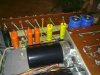
The dots on the caps mark the outside foil, which I determined with an oscilloscope. To do that you simply put the probe's ground clip on one leg of the cap, and the tip of the probe goes on the other leg. Grab the cap and observe on a µV scale. Enhance effect by grabbing an insulated power cord of some equipment on your bench. The cap's orientation with the smaller voltage on the scope is the correct one, and the grounded side of that configuration is the outer foil. To my surprise one of the 160p black beauty caps had an incorrect marking of the outer foil. Measuring the IC MPW caps showed that one can not determine the outer foil from the orientation of the cap's label.
Once my (sw)ellbow gets better I'll do the other monoblock. I hope that's soon.
The restoration came to a halt some time ago, but I'm still on it. I just recently came around ordering the last coupling caps, IC MPW 0.22µF 630V. I installed them today in one amp (320B3) and fired it up, sounds very nice, even though it's mono for now.
The transformer hum is still present with this unit, and after maybe an hour the power transformer gets ~50°C (122°F). I find it very unusual for a McIntosh transformer to hum...
I am very sure that there is no DC present since I run the amp off a step-down isolation transformer. Strange.
Attached you'll find a table with the measured resistor values and the deviation from default in %. Some were measured in circuit (without tubes) and some were measured outside of the circuit when I was replacing the caps. The ones that were measured in circuit and are marked "good spot" are places were one leg of the resistor is either grounded and the other is not connected to anything else (R10, R17 f.e.). Overall it doesn't look too shabby, given that they're close to 50 years old.
The dots on the caps mark the outside foil, which I determined with an oscilloscope. To do that you simply put the probe's ground clip on one leg of the cap, and the tip of the probe goes on the other leg. Grab the cap and observe on a µV scale. Enhance effect by grabbing an insulated power cord of some equipment on your bench. The cap's orientation with the smaller voltage on the scope is the correct one, and the grounded side of that configuration is the outer foil. To my surprise one of the 160p black beauty caps had an incorrect marking of the outer foil. Measuring the IC MPW caps showed that one can not determine the outer foil from the orientation of the cap's label.
Once my (sw)ellbow gets better I'll do the other monoblock. I hope that's soon.
Attachments

dshoaf
That high voltage buzz
Given what you've done so far, the heating of one transformer needs to be a bit more quantified. I'd wonder next what the current draw is between the 2 amps. If there's a heating power transformer, then the heat is coming from something drawing too much current.
Measuring AC current draw would be needed to see if there is a significant problem there, then start working through the power supplies. Since there are so many new capacitor parts, assuming they're ok, I'd also be confirming the biasing of the output tubes, too. That is, I'd be looking for something drawing too much current that would be heating the power transformer. One test could be to monitor AC line current into the amp with and without the output tubes in place while seeing how that affects heating.
On the resistor measurments, they look pretty much ok. The question is whether the operating voltages on each stage meet spec. I'd suspect they should given the variation in resistance readings.
After eliminating those variables would I then start suspecting problems with the power transformer.
Excellent work, too!
Cheers,
David
Measuring AC current draw would be needed to see if there is a significant problem there, then start working through the power supplies. Since there are so many new capacitor parts, assuming they're ok, I'd also be confirming the biasing of the output tubes, too. That is, I'd be looking for something drawing too much current that would be heating the power transformer. One test could be to monitor AC line current into the amp with and without the output tubes in place while seeing how that affects heating.
On the resistor measurments, they look pretty much ok. The question is whether the operating voltages on each stage meet spec. I'd suspect they should given the variation in resistance readings.
After eliminating those variables would I then start suspecting problems with the power transformer.
Excellent work, too!
Cheers,
David
Thank you for your continued input, David! I agree, the transformer issue must be investigated.
With zero Volts at the input of the amp the AC current draw in the primary is 1.40A and the primary voltage is 121V AC. P=U*I comes out as approximately 169W. The service manual states that the amp should consume 140W in this configuration (idle), and 240W at 75W output. Looking back to the first graph in post #7, it seems that the amp was behaving like that before I installed any new parts. The tubes are still the same btw.
For some reason I don't feel comfortable with running the amps without output tubes. Is that really something I can do?
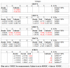
And finally, attached you'll find the deviation from the default voltages (in absolute Volts in the first table, in % in the second one) for various test points.
With zero Volts at the input of the amp the AC current draw in the primary is 1.40A and the primary voltage is 121V AC. P=U*I comes out as approximately 169W. The service manual states that the amp should consume 140W in this configuration (idle), and 240W at 75W output. Looking back to the first graph in post #7, it seems that the amp was behaving like that before I installed any new parts. The tubes are still the same btw.
For some reason I don't feel comfortable with running the amps without output tubes. Is that really something I can do?
And finally, attached you'll find the deviation from the default voltages (in absolute Volts in the first table, in % in the second one) for various test points.
Attachments

Last edited:
dshoaf
That high voltage buzz
A quick glance at the voltage chart: Nothing jumps out at me except maybe the reading that's 10% variant. I wouldn't worry about things until they're getting outside 15% variant. These amps, given that they're likely not to have been used much in years, will have some settling in as the older resistors shed the moisture they've absorbed and now will 'cook' out through heat up/cool down cycles.
The reason I suggested pulling the output tubes was to effectively remove the idling current so you can eliminate it from the current draw through the power supply and, hence, the power transformer. Of course, you're also removing the filament current pulled through the power transformer, too. Then, remeasuring input current draw would tell you if there was a problem there or not. If, in fact, the same problem was there before you started the rebuild, then this test will likely only confirm there's no problem.
Once you get around to the other amp, though, this will provide some extra insight into its typical operation.
Lastly, what kind of voltages, AC and DC, might you measure on the chassis relative to other items you have plugged into the same outlet? This would be measured without interconnects between the units. Reason I ask is whether there's another way that current is running through the transformer.
Cheers,
David
The reason I suggested pulling the output tubes was to effectively remove the idling current so you can eliminate it from the current draw through the power supply and, hence, the power transformer. Of course, you're also removing the filament current pulled through the power transformer, too. Then, remeasuring input current draw would tell you if there was a problem there or not. If, in fact, the same problem was there before you started the rebuild, then this test will likely only confirm there's no problem.
Once you get around to the other amp, though, this will provide some extra insight into its typical operation.
Lastly, what kind of voltages, AC and DC, might you measure on the chassis relative to other items you have plugged into the same outlet? This would be measured without interconnects between the units. Reason I ask is whether there's another way that current is running through the transformer.
Cheers,
David
Last edited:
...
Lastly, what kind of voltages, AC and DC, might you measure on the chassis relative to other items you have plugged into the same outlet? This would be measured without interconnects between the units. Reason I ask is whether there's another way that current is running through the transformer.
Cheers,
David
I run the amp directly off a step-down isolation transformer, nothing else connects to it. I used my Galaxy S smartphone as a source (FLAC), so there is really no way the amp sees any grounds or weird potentials.
I'll try running them without the output tubes once I find some time.