• The move to the new server is done. There are some software and database maintenance updates in process. This has us passing the hat around to help out. We appreciate any donations. Seriously, even a dollar helps. The payment page may be found here - https://www.audiokarma.org/support.html

Refurbishing two MC75 Monoblock Amplifiers

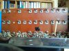
So I did some extensive investigation in the whole resistor ordeal, and finally decided to ditch the CC's entirely and go with modern parts.

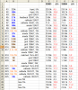
The decisions was motivated and backed by measurements. Measuring voltages and the resistors in-circuit suggested that at least a few were off by quite a bit (see previous posts). After desoldering all resistors I measured them individually and calculated the amount of drift. They almost all were out of spec, and just as expected they all drifted to higher resistances. I acknowledge that desoldering may have contributed to the drift.

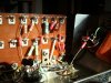
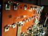
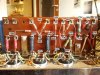
I then repopulated the board with modern resistors. PRP 1/2W MF for the (direct) signal path, Dale RN60D MF for bias duty, Riedon non-inductive WW for the 12BH7's anode load, Takman Rey 1W for the 12AX7's anode load, Kiwame 2W CF for the 12AU7's anode (finding a suitable 30k resistor was surprisingly hard) and Vishay/Phoenix PR02 MF for the 12AU7's and 12BH7's cathode. The latter will likely be exchanged for IRC GS3 and a PR03 at some point. I also have a pair of PRP 100k 1W and a suitable pair of 100k 1W CC should I ever feel the urge to listen to different anode resistors of the 12AX7.
I also replaced the small non-polar caps (100p and 330p) with new silver and mica caps.

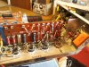
I have yet to fire the amps up, all I did for now was performing the resistance measurements according to the service info (see last pic in post #7), and they all check out fine within 1% or so.

Pitty the board can't be seen anymore once the bottom cover is back on...

I wonder how they sound. Stay tuned.
 

Attachments

  • R_drift.png
    R_drift.png
    71 KB · Views: 215
  • 2011-11-12 11.44.57.jpg
    2011-11-12 11.44.57.jpg
    85.7 KB · Views: 243
  • 2011-11-30 13.28.09.jpg
    2011-11-30 13.28.09.jpg
    92.6 KB · Views: 234
  • 2011-11-30 13.28.45.jpg
    2011-11-30 13.28.45.jpg
    84.7 KB · Views: 231
  • 2011-11-30 15.02.26.jpg
    2011-11-30 15.02.26.jpg
    78.3 KB · Views: 242
  • 2011-12-01 09.48.24.jpg
    2011-12-01 09.48.24.jpg
    107.5 KB · Views: 269
Just fired them up and checked the voltages, they're all really close to the default voltages and well within specs. I already played some Johnny Cash through my test speakers. Sounds promising :yes:

The attached picture shows the newly populated board with the default voltages next to the solder lugs.
 

Attachments

  • annotated_new.jpg
    annotated_new.jpg
    107.3 KB · Views: 257
Lovely work, Rodeodave. This is what I call a 'blueprinted' amp. That is, all the parts have been replaced with the proper value but have been painstakenly tested to know they're right.

Your experience with the drifting resistors is similar to the MC-30s I have rebuilt. The MC-225s I still have have had about 60% of the resistors replaced for similar reasons over the years that I've had them.

Cheers,

David
 
I haven't noticed any word on the inductors, L1 & L2 , that go to the plates of the output tubes. Do they normally not go bad? Has anyone replaced them?

Good thread!

Kennyg
 
So I did some extensive investigation in the whole resistor ordeal, and finally decided to ditch the CC's entirely and go with modern parts.
A wise move for so many reasons. Why go to all that effort (and some expense) with used/old parts.
Great pair of vintage mono-amps.
 
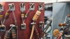
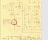
I'm hoping this is a good place to post this question. I'm in the process of rebuilding two MC75's myself and need a recommendation for a replacement capacitor of the one in the attached picture. This is 330PF capacitor that is used in the feedback circuit. Specifically it is C2 and connects to the dedicated smaller winding on the secondary of the output transformer.

Picture and schematic attached.

Thanks in advance.
 

Attachments

  • Feedback Capacitor.jpg
    Feedback Capacitor.jpg
    73.3 KB · Views: 46
  • Schematic.jpg
    Schematic.jpg
    191 KB · Views: 41
I'm hoping this is a good place to post this question. I'm in the process of rebuilding two MC75's myself and need a recommendation for a replacement capacitor of the one in the attached picture. This is 330PF capacitor that is used in the feedback circuit. Specifically it is C2 and connects to the dedicated smaller winding on the secondary of the output transformer.

Picture and schematic attached.

Thanks in advance.
A ceramic type that rarely needs replacement, you could use an NPO 1kv ceramic, or a 630V polypropylene of same value.
 
Thanks PIO. I've wondered for years what was special about that particular capacitor. I have no reason to believe that it is defective so I will leave it. I was in the process of changing the 100uf 3V electrolytic directly behind it and consequently already had one lead of C3 already loose and considered changing it as a precaution.

I gather that polyprop's are inherently temperature stable?

Thank you very much. I don't know what I would do without this forum and helpful people such as yourself. Enjoy this wonderful Sunday!
 
Thanks PIO. I've wondered for years what was special about that particular capacitor. I have no reason to believe that it is defective so I will leave it. I was in the process of changing the 100uf 3V electrolytic directly behind it and consequently already had one lead of C3 already loose and considered changing it as a precaution.

I gather that polyprop's are inherently temperature stable?

Thank you very much. I don't know what I would do without this forum and helpful people such as yourself. Enjoy this wonderful Sunday!
Thank you!
The oem FB loop ceramic caps are understressed and almost never need attention, afaik. The tubular striped caps and elyticaps otoh are all best renewed for restored performance and reliability. All carbon composition resistors should be measured for stated value @ tolerance.
The base voltage measurement standard should be the heater bus voltage @6.3 VAC +-5%, adjusted by variac, for all other voltage measurements.
 
Last edited:
So, when adjusting the bias voltage, you adjust the variac for a plate voltage of 460 volts on the output tubes and adjust the "new" series resistor to whatever it needs to be to achieve the -58 volts on the grid. Following that, you then adjust the heater voltage to 6.3VAC and measure all other voltages? Interesting!! I most likely would have focused on the AC line voltage vs the heater voltage.

PIO, thank you for that tip as well.
 
So, when adjusting the bias voltage, you adjust the variac for a plate voltage of 460 volts on the output tubes and adjust the "new" series resistor to whatever it needs to be to achieve the -58 volts on the grid. Following that, you then adjust the heater voltage to 6.3VAC and measure all other voltages? Interesting!! I most likely would have focused on the AC line voltage vs the heater voltage.

PIO, thank you for that tip as well.
The heater voltage is The one unchanging constant, it determines the operating points of the tubes in reference to all other voltages. Line voltage variations affects all voltage measurements and should be adjusted for 6.3 VAC heater voltage on most tube amps as the baseline to make all other voltage measurements. It is assumed that the recommended line voltage will give the correct voltages, but it's prudent to check the heater voltage to ensure that it's within +-5% tolerance before checking the other voltages. Cdx of tubes, ect, will affect other voltage measurements, the heater voltages, not.
Pardon the pedantacism, the voltage measurements are meaningless without a baseline standard that conforms to an invariable standard, which is the specified heater voltage range for the tube types in use.
 
Last edited:
Thanks PIO. That all makes perfect sense. When testing tubes, you can crank up the heater voltage and make defective tubes look pretty good. I guess it should then reason that an incorrect heater voltage would have significant impacts throughout the amp.

I'll report back once I wrap up the first amp. Getting close.
 
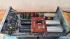
Just completed the rebuild of Amp #1. I replaced all of the resistors. When I rebuild an amp, whether it be stereo or mono blocks, I make both amps (or channels in the case of stereo) identical. This means that when an out of tolerance component is changed in one amp, that I change that same component in the other amp (or channel) even if it is currently in tolerance. I've found that by the time I get through both amps, that the majority of the resistors will need to be changed.

About half of the Black Beauties were well out of spec and those that were in spec were marginal. I chose to replace all of them with Russian PIO's.

This amp tested very well after the rebuild. All voltages were extremely close to nominal with the exception of pins 2&7 and 3&8 of the BH127A. They measured 22V vs 26V and 44V vs 48V respectively. McIntosh made a significant change in resistance values for R11 and R12 and I'm assuming that is the reason for it.

I ran a THD test and at 80 watts it was .18%. At 1% THD, the amp was outputting over 100 watts.

I then did a listen test and it sounds wonderful, as a McIntosh should. Once I get the other amp complete, these will go into my main rig in place of two MC30's. I'm looking forward to hearing the differences between the 30's and the 75's. I'm driving a pair of JBL L300's and I'm thinking the 75's will be a better match, but only time will tell if that will really be the case.

Pictures attached. Feel free to critique my work. I can take it!!
 

Attachments

  • 20230122_122827.jpg
    20230122_122827.jpg
    105.8 KB · Views: 55
  • 20230122_122845.jpg
    20230122_122845.jpg
    88.1 KB · Views: 53
You know you're always welcome to come up here to Angola and finish mine (S/N 328B2 is pretty close to yours!).

I am curious however, if the original Black Beauty caps are film caps, why did you decide to go with PIO?
 
Now that is a good question. I debated that decision for quite some time. I considered everything from orange drops to high dollar film caps. And, of course, I read every post on this site regarding the MC75 / MC 275 on the subject. After realizing that the production of these units spanned the entire 60's and that McIntosh used both bumblebee and black beauties rather inconsistently, I felt that I could go either way. I've seen units with all bumblebee, all black beauty and combinations of both.

Now, what really tipped me to the PIO's was that I already had a stash of them on hand. They are very affordable and seem to be well regarded by most audiophiles.

I am somewhat tempted, when rebuilding unit #2, to experiment with caps a little. It would be quick and easy to temporarily solder in some film caps and compare the two amps side by side.

I would probably just order some IC film caps for this experiment, just because I've seen so many McIntosh amps and preamps rebuilt with them.

One consistent thought on this subject is to use a mix of caps but I'm not sure my ears would be the best test to determine such nuances in sound.

Any recommendations?

Thanks for the comments.
 
My question is because I really don't know. Many claim that their modifications make an audible improvement over the original design, and replacing 70-year-old caps and resistors with new in-spec parts certainly should so is it really the change to metal film resistors and film caps or PIO caps and metal-comp resistors or ....?

I have wondered the same thing though, as I have a late-production MC240 almost completely populated with the Sprague Black Beauty film caps, and I know from photos on-line that they were also built with mostly bumblebee caps, and every mix in-between. Also with four different (although really only two significant) schematics.

So how to proceed with my MC75s? They have been on my bench for I believe two years now and I can't decide what capacitors to order. The power supply is easy, I've already spent the money for the Authenticap twist-loc and feel it's worth the extra $$, the resistors will all be carbon-comp to have the same delta-T as the original, but that still leaves a couple-dozen caps and many of them in the signal path.

When making my part-list, I decided I'll be ordering every cap and resistor in the amps. If one is in-spec in the first amp, it might be out in the second, and if one is replaced then they both are to ensure symmetry between the channels. Everything is removed anyway to use new chassis. Therefore I can choose film or PIO, or any capacitor type I want because I'll be replacing them both.

So that led me to asking the question as I too have seen both cap styles in these amps and wonder if it will make a difference. I guess I can look at as many under the deck photos as I can find to see if there are any caps that are always film or always bumblebee, but even that won't tell me why or if it'll make a difference, or if it is only in the samples I've found.

I know that I could try different caps, but experience has shown that once it's complete and buttoned-up I won't open it again, probably ever, so I can cross experimentation off of my list. I still have to order those caps, ... probably will stick with same-type replacements to my amps' original build, which only contain (2) Black Beauty (Sprague 160P) caps and the rest Bumblebee.

BTW, I've also read (and it is on the internet so it must be true, ... ;-) ) that bumblebee caps aren't PIO unless there is a vent tube showing on one end, which none of mine have so I'm thinking I need to cut a couple open to see what they truly are also.
 
As I've said in other threads, I seriously doubt Frank and Gordon spent much time auditioning various passive component options, I'd rather suppose they selected the best economically available quality production parts then available for reliability.
I'd be inclined to do likewise with the same protocols with parts now available.
 
As I've said in other threads, I seriously doubt Frank a d Gordon spent much time auditioning various passive component options, I'd rather suppose they selected the best economically available quality production parts then available for reliability.
I'd be inclined to do likewise with the same protocols with parts now available.

Probably true and a good point.

Likely the components were chosen based on good commercial-quality parts using engineering best-practices of the time, prototyped then pre-production builds, listening and testing, if it was good then it became the production spec. As different parts became available (or unavaliable) the new part option was tested, if okay it became a running change or an alternate source for purchasing & production.

There is also the possibilty that a problem was found and a part / parts upgraded to a better part that doesn't have the same problem in-circuit, but then we would see more consistency I'd expect where all amps after S/N xxxx would have the substituted part and I haven't seen this yet, plus there would likely be a SB that recommends the change to prevent whatever problem occurred after the amplifier was released. If we had the luxury of lining up many amps by production date we might see a slow change from year to year a component or two at a time as Sprague changed their product and the part bin ran out and new ones replaced old, maybe McIntosh wasn't great at FIFO and occasionally an older box of components would be opened and put on the line, hard to tell.

If Sprague produces two different spec. film caps, one the 160P "Black Beauty" and the other in a striped "bumblebee" package it might actually be the same cap with a different spec for marking, and either acceptable part numbers for McIntosh to order. This is my favorite theory anyway as everything else seems to be fairly consistent in the tube-amp builds. Or maybe one is tighter tolerance and not necessary for the design (but still an alterative for purchasing and something they used in another build), but either way it didn't seem to matter to McIntosh.

I'm still in the "need to order those" stage, doesn't seem like it matters too much so I plan to replace everything with original type in my amp as available at this point.
 
Back
Top Bottom