

You are using an out of date browser. It may not display this or other websites correctly.
You should upgrade or use an alternative browser.
You should upgrade or use an alternative browser.
Replacing VFETs with MOSFETs
 )
)


Good news and bad news. The good news is that I've managed to get distortion down by correctly compensating for ripple in the power supply. I had overcompensated the variation and this led to ripple in the bias current. I was able to optimize this and now the distortion at 2 W is the specified 0.01% as it is with the VFET amp. It rises to 0.06% at 20 W. Clipping is at 50 W with one channel driven. I ****ed up the mod so I blew up two IRFPs in the process.
The bad news is that the thermal runaway of the HEXFETs is significant. Even with the heat sink getting warm the idle bias current doubles. The datasheet suggests that it will increase tenfold when really hot. So I've decided to go try the 2SJ161/2SK1057 that failed to work the previous attempt. This failure was caused by my misobservation of the pinout of audio power MOS devices. This decision necessitates the reinstatement of the additional power supply rails of +/- 75 V in order to be able to drive the laterals correctly as their V(GS) is just above zero volts.
Tjerk, 9ZZ
The bad news is that the thermal runaway of the HEXFETs is significant. Even with the heat sink getting warm the idle bias current doubles. The datasheet suggests that it will increase tenfold when really hot. So I've decided to go try the 2SJ161/2SK1057 that failed to work the previous attempt. This failure was caused by my misobservation of the pinout of audio power MOS devices. This decision necessitates the reinstatement of the additional power supply rails of +/- 75 V in order to be able to drive the laterals correctly as their V(GS) is just above zero volts.
Tjerk, 9ZZ

+1 - also following with great interest.I don't have anything useful to say, but just want to let you know this is one of the most potentially useful and interesting threads I've seen on AK in years. Do please continue with your efforts... I'm on the edge of my seat even if I don't say much along the way.

There is a result! And it's a good one! I managed to get my laterals (2SJ161/2SK1057) properly biased and they put out a healthy 47 W into my 8R dummy load. I also left out the additional supply voltages. The thermal stability is much better than with the HEXFETs. While it doubles when hot there is no thermal runaway. I was afraid the biasing would be an issue but my sims proved correct. The only issue that I'm facing is that the distortion is rather high at higher power levels. At 2 W it's 0.01% as with the VFETs but at 20 W it's at 0.2%. Just below clipping it's still that much. The VFETs remain at the low value all the way to clipping. Maybe this is caused by the supply ripple in the driver. Maybe the sim can shed some light on this.
Tjerk, 9ZZ
Tjerk, 9ZZ

 Great work so far, loving the thread.
FootFungus
Super Member
You might try boosting the bias to idle around 80ma since its going to end up around there eventually. Alternatively, you might need to boost the idle or drive current a bit in the preceding stages to drive the gate capacitance on the laterals.
After chasing several red herrings with my wonderful Lindos LA100 audio test set I finally managed to get consistent values for distortion. I now use the headphone jack instead of my painfully crafted x10 attenuator on my 8R dummy load. Advantage is that I can remove the load by disconnecting it with the speaker selector switch. The VFET amp is 0.01% at 2 W (as per spec) but my 2SJ161/2SK1057 mod amp only gets that on the left channel. R_Ch is at 0.2% and more at higher power levels. I discovered that the LA100 has a SCOPE BNC socket that has the output signal of its distortion meter circuit. With the SYNC signal I can see on my trusty Philips PM3055 what the distortion looks like. This provides a wealth of information. First of all, L_Ch has a parasitic oscillation at 20 kHz that is synchronized with the mains frequency! When I tried to delve into that it disappeared. The other channel looks like it has crossover distortion. Upping bias current does nothing. Thing is that both channels are more or less identical component-wise so just why R-Ch is misbehaving is beyond me. Maybe it has something to do with the driver being operated at near zero output voltage. Note that I use the power input jacks at the rear so I only test the power amp.
Tjerk, 9ZZ
Tjerk, 9ZZ

atmasphere
Active Member
Maybe a dumb question but are you sure your gate stop resistors are a large enough value?

jeromach
With sufficient thrust, ducks fly just fine
Goed bezig!
It seems I have a car again (for as long as it takes, maybe not that long...), so I'd love to come by one of these days to take a listen (and look) at all the goodies. Very happy btw that the original VFET is behaving so well. And it seems you're just that far away from coping with the 4650M-FET too
It seems I have a car again (for as long as it takes, maybe not that long...), so I'd love to come by one of these days to take a listen (and look) at all the goodies. Very happy btw that the original VFET is behaving so well. And it seems you're just that far away from coping with the 4650M-FET too
Gate stoppers are unchanged from the original (22R). I do have some parasitics but I believe that is mainly caused by the lack of power supply bypassing on the board itself. I will add these at a later stage to try to kill those. However, this is not the issue I'm facing. I have two almost (famous last words...) identical amps and they behave differently. L_Ch has 0.0091% at 2 W and R_Ch is 0.24%! See the pics below:Maybe a dumb question but are you sure your gate stop resistors are a large enough value?
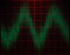
This is how 0.0091% distortion looks like

0.24% distortion
The top one is just noise and the second harmonic (L_Ch) and the bottom one is some kind of crossover distortion. I found small differences in V(GS) (Q311: 0.84 V, Q361: 0.74 V) so I will swap these to see what happens. I did look at the drive (V(GS), 1 V/div):

Q311

Q361
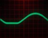
Q312
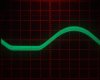
Q362
It is a wide trace because it rides on the supply voltage. I believe the parasitics in the drive for Q361 (bad channel) are caused by my probe. There is an additional capacitor that can be removed which could be the cause but I want to swap out the two 2SK1057s first. Maybe in the end it is a biasing issue...
Now I'm going to watch TV (Mr. Robot 408 Request Timeout).
Tjerk, 9ZZ
atmasphere
Active Member
It shouldn't be any surprise that two channels are different, this is going to be true unless your devices are well matched. It looks to me like a driver isn't working right in your waveforms.
I can think of one solution for this: reinstate the driver power supply. Only this time use a much lower value of maybe a PN junction drop. Or a zener diode. But this complicates the circuit again. I'm just so surprised that (if that actually is the cause) the effects of just a small change in V(GS) are so extreme. Also, why is V(GS) of the P-channel MOSFET only -0.24 V?!? The Hitachi datasheets suggest they should be more or less identical (min 0.15, max 1.45 V). So yes, maybe this simple solution is too critical...
Tjerk, 9ZZ
Tjerk, 9ZZ
There is an advantage of using the additional power supply: the mod becomes more universal and less dependent on transistor parameters:
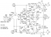
The simulation now totally behaves because of the P-channel not drawing any current when it should be cut off. But first I'll try that transistor swap. To be continued...
Tjerk, 9ZZ
The simulation now totally behaves because of the P-channel not drawing any current when it should be cut off. But first I'll try that transistor swap. To be continued...
Tjerk, 9ZZ
FootFungus
Super Member
On the Hafler amps using the Hitachi laterals, they used much higher gate stopper resistors - 470 ohms. B&K used even higher 1k to 1.5k ohms. You may need to bump those up if the oscillations persist.
It could also be a matter of the long leads to the power supply caps. There is no decoupling on the board at all. If the parasitics persist I will add those first. There is dispute over the value of stopper resistors. Too large could also cause instability. Besides, this is a compound topology, not a source follower as with the Hafler. But it's always good to keep in mind.
Tjerk, 9ZZ
Tjerk, 9ZZ
This project is getting out of hand... Even so, looks like I found a solution for my woes. This is the final attempt, if this doesn't work I quit. Simulations are patient.
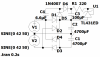
I've decided to use a TL431 as additional power supply and keep the original setup with the charge pump:
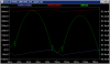
I also compensated the supply voltage ripple just like I did with the IRFPs:

I found a pretty well compensated solution with E12 resistor values keeping in mind the V(GS) difference of the P- and N-channel transistors:
Finally, all the design files (including the TL431) for the whole project are in the ZIP file.
I quickly tested my current setup and I found that now also L_Ch has crap distortion performance. It is also dependent on the mains voltage. That is not good... Tomorrow I'll fire up the old Weller to change everything, now hopefully for the last time.
Tjerk, 9ZZ
I've decided to use a TL431 as additional power supply and keep the original setup with the charge pump:
I also compensated the supply voltage ripple just like I did with the IRFPs:
I found a pretty well compensated solution with E12 resistor values keeping in mind the V(GS) difference of the P- and N-channel transistors:
Finally, all the design files (including the TL431) for the whole project are in the ZIP file.
I quickly tested my current setup and I found that now also L_Ch has crap distortion performance. It is also dependent on the mains voltage. That is not good... Tomorrow I'll fire up the old Weller to change everything, now hopefully for the last time.
Tjerk, 9ZZ
