• Please note that Audiokarma will be offline briefly for updates early on Monday morning, September 28th.

Russco Studio Pro Plinth Build

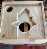
Made some progress today, this is a rough cut out of the first layer plate, it rides directly against the top plate….It clears all the internal mechanisms and the electronics.

This first layer is thick enough to allow the motor plate movement, this will allow for a more enclosed second layer, the open end will have to remain open for several layers, to clear the “gear shift” mechanism. Eventually the layers will only have a hole for the motor, and ventilation.

Next step, use this rough cut out as pattern for a cleaner example, and then start adding layer after layer….
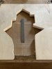
F6D6E0EC-C610-413F-B96D-152966F319C1.jpeg
 
Made a clean copy of the above, the pattern was cut out then cleaned up with a router. The tight corners were cleaned up and shaped with a very sharp chisel, yes by hand ;).

Using a router is not necessary, neither is using a chisel to shape the corners, it’s just in my nature can’t help myself :crazy:

Here’s a view on how it will look right under the top plate….now it’s time to make a few copies of the weird cut out, it’s probably going to take 3 similar to clear everything then the rest of the layers will just have one hole for the motor and another for tonearm access.

4E1016F0-9BA3-4203-9D90-13884404F76E.jpeg
 
BTW

Should have mentioned that for anyone with a Studio Pro I’d be glad to share a template with you, should work for a Cue Master also. Would probably save someone considerable time :dunno:

Went through several design iterations, even vertical :blah: but it’s certainly not rocket science ;)

If you’re interested just let me know.

VR
Andy
 
Looking good Andy! Is the plate installed upside down? Tonearm cutout should be on the right along with the hole for switch clearance.
It's nice that your offering the templates to other Russco owners. That part looks to be a royal PIA.

BillWojo
 
Good eye Bill, yes it’s reversed, just laying in there for the photo, not consciously aware of what I’m doing :)

For those wondering about why not just cut a “oblong hole” big enough to clear everything?

The answer is, yes it could be done that way, but leaving the most material in contact with actual table as possible is the chosen approach here. This is done to take advantage of material contact or transference, capturing as much noise and vibration transfer as possible….

Subsequent layers could be done without all the difficult cuts, leaving small chambers, and actually the access hole underneath the tonearm gets bigger as it goes down through the layers.

If you’re designing/building one of your own either approach is valid, just make sure there’s a connection so that transference is achieved, otherwise the mass is not required, as has been pointed out ;)


VR
Andy
 
Last edited:
The layers are just time and effort now, the builder has to decide how to attach them together, if so desired. The can stacked, but I prefer to alternate the grain and screw most of them together.

Glue is fine, but I prefer not to use it, and acoustic caulk works well, but it also becomes glue of sorts.

In my approach the first layer (contact board) is the hardest one, the rest can be pieced together and in my opinion, provides the best results. I’ll post so pictures of the layer stack shortly…

Decided to work on the visible portion today, as I’ve said most of my work is with handtools, here’s some highlights:

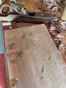
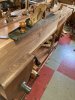
Here’s the rough board, which is worked with a Scrub plane:

0B6E4FB2-B462-41C8-898A-8030C1537D1B.jpeg

Scrub planes have an open mouth and a round iron (blade) which removes a lot of material…they come in wood and metal versions

792FF103-287F-4EB7-BE09-6F7812A5DEF4.jpeg

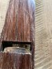
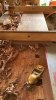
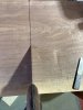
In the next steps the planes get less aggressive until one can’t even see any marks from the iron, called plane tracks. The goal is to get the board flat, and then square up one edge. Use the plane bottom and something called Winding Sticks, to check for flatness and to see if the board is twisted. Note the light showing underneath the plane edge, that needs to be almost zero.E6EF4A70-8035-4965-803D-37E203531143.jpeg3FEAB5FA-2F17-444D-BB7E-69823EF1ACC7.jpeg

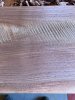
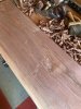
What gets revealed is worth the effort, note the purple hues, that only exists in none kiln dried Black Walnut
13EF3A3D-92E0-4E6F-B299-2CDD2529D946.jpeg


F40766BA-FB22-4AC0-A81D-BADA9938BA9E.jpeg

Continued below….
 
When one side of the board is flat, a square reference edge is put on it3D575D00-5B97-4E2F-911B-32372FD633EC.jpeg

A620805F-0156-4D1F-9902-51C995958E0D.jpeg

Then the board can be sized to width and thickness

35AD5B02-9447-42D3-8DA7-94146975566D.jpeg 2492C0FC-E873-4F43-9AD6-B97835A1BA9C.jpeg

After all that we have our boards:thumbsup: This particular wood has been in storage for over 80 years:eek:

8A10FE07-00AE-4B92-A9AD-B741B3328ACF.jpeg

I’m always amazed when the beauty starts to appear from a rough piece of lumber, makes me understand the reverence the Shakers had for their own woodworking and what they produced.


VR
Andy
 
Wow Andy, your a master craftsman! That's looking beautiful.
How do you use the Winding sticks? Visually sighting across the top edges?
Pretty neat that your the first to see the inner beauty of that 80 year old plank. Must be a story behind where you got it from.

BillWojo
 
Thanks, appreciate the kind words….

Winding sticks are difficult to make but easy to use. They have to be precisely made, in fact I check them with a machinist straight edge. You have the general concept, they are positioned on each end and centered, then one looks to see if one edge is higher than the other.

One photo of winding sticks in use, the other is me making sure they are still flat with a straight edge:

32B00016-E2E1-401F-889B-FA924857025C.jpeg 074C4579-60FF-41F3-911C-54BE8896BB56.jpeg

The wood came from my neighbor who is around 90 years old, and it belonged to her father, who was a master woodworker. It was part of his special collection, that he never got around to using :(
 
When one side of the board is flat, a square reference edge is put on itView attachment 2302800

View attachment 2302802

Then the board can be sized to width and thickness

View attachment 2302811 View attachment 2302816

After all that we have our boards:thumbsup: This particular wood has been in storage for over 80 years:eek:

View attachment 2302833

I’m always amazed when the beauty starts to appear from a rough piece of lumber, makes me understand the reverence the Shakers had for their own woodworking and what they produced.


VR
Andy
Beautiful work! Are you planning on keeping the contrast of the sapwood? I personally love the contrast.
 
Beautiful work! Are you planning on keeping the contrast of the sapwood? I personally love the contrast.

Thanks, and appreciate your input:

Personally really like the sapwood especially in walnut and cherry, and don’t consider it a flaw but then again I don’t consider knots and such as flaws in most cases.

Wouldn’t feature a knot in certain aspects/locations but understand that some don’t find sapwood and/or knots appealing.

VR
Andy
 
Yea, I really like the sapwood as well. Now I was talking to my friend about this and he really liked the walnut with the knot in it. Go figure. Anyway, I think the only waste that comes from that plank will be in the form of sawdust and shavings.

BillWojo
 
Yea, I really like the sapwood as well. Now I was talking to my friend about this and he really liked the walnut with the knot in it. Go figure. Anyway, I think the only waste that comes from that plank will be in the form of sawdust and shavings.

BillWojo

Things like knots add character, and makes it unique, but are always discussion items; people hate or love knots;)

Here’s my Fisher 800c cabinet, don’t think it would be as dramatic without the knots:

566EFC99-4DB2-4085-A3A4-617886214E54.jpeg
 
Otherwise occupied for the last few days but have worked out the clearance for the layers.

This Russco has the shorter motor, so it took 5 layers of 3/4” to clear the motor, some Russco’s have the same motor as the ROK Rondine Deluxe ( along with a plethora of other high end tables) so it’s going to take another layer to clear one of those.

The large hole in the lower center is the motor ventilation, the other large hole (upper left photo) is for tonearm access and it gets smaller towards the plate. The two smaller holes allow access to the platter shaft well, and the speed shift mechanism.

Each layer has the face grain turned in opposite directions, just need to finish the tonearm access hole and fasten the layers together. My preference is to use a sound deadening material between select layers and screw them together…

Once their fastened together they’ll get trimmed/sized to fit into the inner box (the plywood model) and it then fits inside the Walnut….

FFB70E76-6CAC-4535-A50B-DC5E9D5298A1.jpeg 1550232A-70FA-4447-8BC8-A1CF377C5563.jpeg
 
Looks good Andy, going to be a lot of solid wood in that. Any idea what it might weigh yet?
The later Russco TT used the Nidec Japanese made motor. Looks to be a well built motor and I'm sure it was much cheaper for Russco to purchase than the USA built Bodine motor. Knowing the Japanese penchant for building precision equipment I'll wager there isn't much difference in the performance.

BillWojo
 
No not sure on the weight yet, but it’s certainly going to be heavy ;)

Yeah also assume that the Nidec motor is exceptional, had it running changing speed to check clearances and forgot it was on, it reminded me when I rested my hand on the spinning shaft :eek: it’s extremely quiet and there’s no perceivable vibration…..

When it’s all together I’ll hook it up to my old tube Wow & Flutter tester just to satisfy my curiosity :naughty:

VR
Andy
 
Andy, that would be interesting to get measurements from one of these restored TT units. I don't think I have ever seen anyone do that before.
I assume that is used with a special test record?

BillWojo
 
Not sure whether one can/should call these measurements, but i believe they have some value when checking if a modification had an influence on W&F.
Svalander idler.jpg

This is from an original idler retreaded by Svalander (Sweden), for which i made a POM (Delrin) bearing and trued the rubber while it was on the lathe.
 
;)
Andy, that would be interesting to get measurements from one of these restored TT units. I don't think I have ever seen anyone do that before.
I assume that is used with a special test record?

BillWojo

Yeah Bill, went through a few “Test records” before I found one that suited my requirements, only thing that’s frustrating about it is that the 3k freq portion isn’t very long, have to be quick;)

Originally purchased the Wow/Flutter tester just to satisfy my curiosity, since my turntable collection included several drive types, wanted to see how they compared numbers wise….
 
Not sure whether one can/should call these measurements, but i believe they have some value when checking if a modification had an influence on W&F.
View attachment 2308783

This is from an original idler retreaded by Svalander (Sweden), for which i made a POM (Delrin) bearing and trued the rubber while it was on the lathe.

I’d call that observational data, especially if you have sample data before and after the changes :thumbsup:

VR
Andy
 
Back
Top Bottom