

You are using an out of date browser. It may not display this or other websites correctly.
You should upgrade or use an alternative browser.
You should upgrade or use an alternative browser.
SA-8800 protection mode help
- Thread starter alexhastings
- Start date


alexhastings
Active Member
Put Q4 in first, relay pulls in. then added Q3, and relay still pulls in! Trying some sound through it now - it seems to be happy!
alexhastings
Active Member
Thanks a bunch for all your help!

I_Wanna_Rock
Active Member
Congrats, Alex and thank you for making me aware of your thread. I learned a lot, (like I'm not ready lol) just following along. Really fascinating!Thanks a bunch for all your help!
-John
alexhastings
Active Member
You're welcome! I'll continue to document my notes here on this thread as I fix up the amp, just in case anyone can use it in the future! (I know old 8800 threads were super helpful to me, and continue to be!
alexhastings
Active Member
Hi everyone - back for more! I'm working on the EQ board now - GWF-117 (it's GWF-113 in the service manual. but they seem to be identical). When testing it out, I get clear sound through the R channel, and a loud hum and very low signal from the L. This happens on both phono 1 and 2 inputs, and the tuner/aux inputs all sound good, so I think the issue is on the EQ board...
I've recapped it already, and just double checked that - looks like it's all ok. Solder joints look ok too. I've been checking voltages to see if I can find a bad transistor, but the voltages look ok so far too - I guess there could be a bad transistor anyways?
As for getting replacements, do Q1/Q3, Q5/Q7, Q6/Q8, Q2/Q4 all have to be gain matched?
Was also having trouble finding a good replacement for 2SC2602 and 2SA1114... The 512-KSC1845FTA and 512-KSA992FBTA looks like they mostly work?
I've recapped it already, and just double checked that - looks like it's all ok. Solder joints look ok too. I've been checking voltages to see if I can find a bad transistor, but the voltages look ok so far too - I guess there could be a bad transistor anyways?
As for getting replacements, do Q1/Q3, Q5/Q7, Q6/Q8, Q2/Q4 all have to be gain matched?
Was also having trouble finding a good replacement for 2SC2602 and 2SA1114... The 512-KSC1845FTA and 512-KSA992FBTA looks like they mostly work?

petehall347
the brandy coffee man
try with the top cover back on to see if hum changes

How can a bad transistor introduce hum? Do you get it with the inputs open or connected? Shielding at the EQ input loose?I guess there could be a bad transistor anyways?
alexhastings
Active Member
Whoa, so the hum does appear to have been caused by the top cover being off... weird - didn't expect that! I think the missing channel might have been a cable problem too - swapped the cable out, and the channel dropout solved itself too!
alexhastings
Active Member
The board ID on my SA-8800 (Type S/G) was AWR-193, instead of the AWR-182 in the service manual. As far as I could tell, the boards are identical - I had no problem using the service manual board layout.
Note: on this power board, the power caps retain their voltages after the unit is turned off! If the caps aren't drained, they will inevitably discharge in a not ideal way! After a couple of accidental discharges onto the heat sink (loud pop!), I started discharging them manually. I used one of the old 370ohm 5W resistors I took out off the board. A 10-20ohm 5W resistor would be even better! Using alligator clips, connect one end of the resistor to the chassis, and the other end to pins 20, 22, 23 and 25 (one at a time!). With the 370ohm resistor, each cap took 30-40secs to get down to a safe level (under 5V). It would take much less time with a 10-20ohm resistor. You definitely need a 5W one though - with a 1/4W resistor, you'll just burn it up. You will feel the resistor heat up as it discharges the cap!
Ended up replacing all silicone except for D1-8, all electrolytic caps except for the big ones (C5-8), and all of the /!\ marked resistors in the circuit. CSV of the replacement here:
------------------------------------------------------------------------------------------------
Component Name,Schematic Value,Digikey Replacement Part No,Mouser Replacement Part No,Notes
C1,0.01u/400V,,505-MKS4.01/630/10,
C10,220u/80V,,667-EEU-FS1K221,
C13,100u/10V,493-1861-ND,,Replaced with 100u/35V
C14,47u/63V,,647-UFG1J470MPM1TD,
C15,47u/63V,,647-UFG1J470MPM1TD,
C18,47u/50V,,647-UFG1J470MPM1TD,
C19,47u/50V,,647-UFG1J470MPM1TD,
C2,0.01u/400V,,505-MKS4.01/630/10,
C22,2.2u/50V,,505-MKS22.2/50/5,
C23,1u/63V,,661-E-101L1R0ME11D,
C24,100u/10V,493-1861-ND,,Replaced with 100u/35V
C25,470u/6V NP,P1146-ND,,
C3,0.01u/400V,,505-MKS4.01/630/10,
C9,220u/80V,,667-EEU-FS1K221,
D1,30D2 (GP-25D),,863-1N5404G,
D10,10E2 (SIB01-02),,863-1N4004G,
D11,10E2 (SIB01-02),,863-1N4004G,
D12,10E2 (SIB01-02),,863-1N4004G,
D13,1S2471,,863-1N4004G,
D14,1S2471,,863-1N4004G,
D15,WZ-150,,512-1N5245B,
D16,WZ-061,,512-1N5234B,
D17,1S2076 (1S1555),,512-1N4148,
D18,1S2076 (1S1555),,512-1N4148,
D19,1S2076 (1S1555),,512-1N4148,
D2,30D2 (GP-25D),,863-1N5404G,
D3,30D2 (GP-25D),,863-1N5404G,
D4,30D2 (GP-25D),,863-1N5404G,
D5,30D2 (GP-25D),,863-1N5404G,
D6,30D2 (GP-25D),,863-1N5404G,
D7,30D2 (GP-25D),,863-1N5404G,
D8,30D2 (GP-25D),,863-1N5404G,
D9,10E2 (SIB01-02),,863-1N4004G,
Q1,2SC945A,,512-KSC2383YTA,
Q10,2SA904A,,512-KSA992FBU,
Q11,2SK34,,610-1N5306,cathode to side with two shorted leads
Q12,2SK34,,610-1N5306,cathode to side with two shorted leads
Q13,2SD712,,512-KSC2073TU,added heat sink with mica insulator
Q14,2SB682,,512-KSA940TU,added heat sink with mica insulator
Q15,2SC945A,,512-KSC945CYTA,
Q16,2SA733A,,512-KSA1013YBU,
Q2,2SC1384,,512-KSC2690AYSTU,
Q3,2SC945A,,512-KSC945CYTA,
Q4,2SC945A,,512-KSC945CYTA,
Q5,2SK34,,610-1N5306,cathode to side with two shorted leads
Q6,2SK34,,610-1N5306,cathode to side with two shorted leads
Q7,2SC1735,,512-KSC2383YTA,
Q8,2SA850,,512-KSA1013YBU,
Q9,2SC1914A,,512-KSC2383YTA,
R1,10 (1W),,CPF210R000FKEE6,
R16,390 (5W),,71-CW005390R0JE73,
R17,390 (5W),,71-CW005390R0JE73,
R18,470 (5W),,71-CP0005470R0JE14,
R19,470 (5W),,71-CP0005470R0JE14,
R2,10 (1W),,CPF210R000FKEE6,
R5,47 (1W),,594-MBE04140C4709FC1,
R8,680 (1W),,71-CPF2680R00FKE14,
------------------------------------------------------------------------------------------------
All transistors were ECB configuration, so the replacements were all basically 1:1. Had to take care to match the orientation of the BJTs. Q5-6 and Q11-12 JFETs were replaced with current regulator diodes, which worked perfectly. The replacement plan for those is attached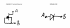
Note that all transistors tested ok, even when they were proven defective… Probably can't rely on transistor testing to tell you if the existing ones are good or bad. Q13 and Q14 100% need heat sinks - they get very hot! I used the Mouser #532-504222B00 heat sinks and #534-4673 insulators, and some short 4-40 screws and nuts to hold them together. I had to dremel off the fins about halfway to get these to fit - I'm sure better heat sinks are available out there!
I had to remove the power cap holder to get to C1 and C2… If I ever replace the power caps, or D1-8, I'll have to move it again - that was probably the most pain in the ass part of working on this board, because even with all the screws out, it's still pretty much captive to the transformer and hard to move around!
I'll write up notes on the other boards in the next couple days!
Note: on this power board, the power caps retain their voltages after the unit is turned off! If the caps aren't drained, they will inevitably discharge in a not ideal way! After a couple of accidental discharges onto the heat sink (loud pop!), I started discharging them manually. I used one of the old 370ohm 5W resistors I took out off the board. A 10-20ohm 5W resistor would be even better! Using alligator clips, connect one end of the resistor to the chassis, and the other end to pins 20, 22, 23 and 25 (one at a time!). With the 370ohm resistor, each cap took 30-40secs to get down to a safe level (under 5V). It would take much less time with a 10-20ohm resistor. You definitely need a 5W one though - with a 1/4W resistor, you'll just burn it up. You will feel the resistor heat up as it discharges the cap!
Ended up replacing all silicone except for D1-8, all electrolytic caps except for the big ones (C5-8), and all of the /!\ marked resistors in the circuit. CSV of the replacement here:
------------------------------------------------------------------------------------------------
Component Name,Schematic Value,Digikey Replacement Part No,Mouser Replacement Part No,Notes
C1,0.01u/400V,,505-MKS4.01/630/10,
C10,220u/80V,,667-EEU-FS1K221,
C13,100u/10V,493-1861-ND,,Replaced with 100u/35V
C14,47u/63V,,647-UFG1J470MPM1TD,
C15,47u/63V,,647-UFG1J470MPM1TD,
C18,47u/50V,,647-UFG1J470MPM1TD,
C19,47u/50V,,647-UFG1J470MPM1TD,
C2,0.01u/400V,,505-MKS4.01/630/10,
C22,2.2u/50V,,505-MKS22.2/50/5,
C23,1u/63V,,661-E-101L1R0ME11D,
C24,100u/10V,493-1861-ND,,Replaced with 100u/35V
C25,470u/6V NP,P1146-ND,,
C3,0.01u/400V,,505-MKS4.01/630/10,
C9,220u/80V,,667-EEU-FS1K221,
D1,30D2 (GP-25D),,863-1N5404G,
D10,10E2 (SIB01-02),,863-1N4004G,
D11,10E2 (SIB01-02),,863-1N4004G,
D12,10E2 (SIB01-02),,863-1N4004G,
D13,1S2471,,863-1N4004G,
D14,1S2471,,863-1N4004G,
D15,WZ-150,,512-1N5245B,
D16,WZ-061,,512-1N5234B,
D17,1S2076 (1S1555),,512-1N4148,
D18,1S2076 (1S1555),,512-1N4148,
D19,1S2076 (1S1555),,512-1N4148,
D2,30D2 (GP-25D),,863-1N5404G,
D3,30D2 (GP-25D),,863-1N5404G,
D4,30D2 (GP-25D),,863-1N5404G,
D5,30D2 (GP-25D),,863-1N5404G,
D6,30D2 (GP-25D),,863-1N5404G,
D7,30D2 (GP-25D),,863-1N5404G,
D8,30D2 (GP-25D),,863-1N5404G,
D9,10E2 (SIB01-02),,863-1N4004G,
Q1,2SC945A,,512-KSC2383YTA,
Q10,2SA904A,,512-KSA992FBU,
Q11,2SK34,,610-1N5306,cathode to side with two shorted leads
Q12,2SK34,,610-1N5306,cathode to side with two shorted leads
Q13,2SD712,,512-KSC2073TU,added heat sink with mica insulator
Q14,2SB682,,512-KSA940TU,added heat sink with mica insulator
Q15,2SC945A,,512-KSC945CYTA,
Q16,2SA733A,,512-KSA1013YBU,
Q2,2SC1384,,512-KSC2690AYSTU,
Q3,2SC945A,,512-KSC945CYTA,
Q4,2SC945A,,512-KSC945CYTA,
Q5,2SK34,,610-1N5306,cathode to side with two shorted leads
Q6,2SK34,,610-1N5306,cathode to side with two shorted leads
Q7,2SC1735,,512-KSC2383YTA,
Q8,2SA850,,512-KSA1013YBU,
Q9,2SC1914A,,512-KSC2383YTA,
R1,10 (1W),,CPF210R000FKEE6,
R16,390 (5W),,71-CW005390R0JE73,
R17,390 (5W),,71-CW005390R0JE73,
R18,470 (5W),,71-CP0005470R0JE14,
R19,470 (5W),,71-CP0005470R0JE14,
R2,10 (1W),,CPF210R000FKEE6,
R5,47 (1W),,594-MBE04140C4709FC1,
R8,680 (1W),,71-CPF2680R00FKE14,
------------------------------------------------------------------------------------------------
All transistors were ECB configuration, so the replacements were all basically 1:1. Had to take care to match the orientation of the BJTs. Q5-6 and Q11-12 JFETs were replaced with current regulator diodes, which worked perfectly. The replacement plan for those is attached
Note that all transistors tested ok, even when they were proven defective… Probably can't rely on transistor testing to tell you if the existing ones are good or bad. Q13 and Q14 100% need heat sinks - they get very hot! I used the Mouser #532-504222B00 heat sinks and #534-4673 insulators, and some short 4-40 screws and nuts to hold them together. I had to dremel off the fins about halfway to get these to fit - I'm sure better heat sinks are available out there!
I had to remove the power cap holder to get to C1 and C2… If I ever replace the power caps, or D1-8, I'll have to move it again - that was probably the most pain in the ass part of working on this board, because even with all the screws out, it's still pretty much captive to the transformer and hard to move around!
I'll write up notes on the other boards in the next couple days!

Note that all transistors tested ok, even when they were proven defective… Probably can't rely on transistor testing to tell you if the existing ones are good or bad.
which transistor tester?
alexhastings
Active Member
I was just using the diode test function on my multimeter to test base-emitter and base-collector. Maybe there is a better way?which transistor tester?
While the 6 way diode test IS indicative of gross failures, it is not indicative of successful operation.
https://www.audiokarma.org/forums/i...lar-junction-transistor-testing-basics.43186/
and my post #11 in the thread.
https://www.audiokarma.org/forums/i...lar-junction-transistor-testing-basics.43186/
and my post #11 in the thread.
alexhastings
Active Member
I definitely concur with that!
alexhastings
Active Member
The board ID on my SA-8800 (Type S/G) was GWH-128, instead of the GWH-115 in the service manual. As far as I could tell, the boards are identical - I had no problem using the service manual board layout. This was a working board when I started with it, so I was able to test sound after every replacement.
Opted to replace all /!\ marked components on this board. I was going to have to pull them to test them, and if I was going to do that, I might as well put new ones back in! The replacements were pretty straight forward, and just about every component measured to spec when I took it out!
I also replaced the VR5-10 pots, since a scratchy old idle current pot has the potential to blow up an output transistor during adjustment. I opted for the more expensive circular pots in my build - mainly because they were 4-turn pots, giving me more adjustment resolution! I've included the cheaper 1-turn pots in my CSV file as well, just in case the 4-turn ones aren't available, or there are budgetary constraints! I ordered and checked all these pots - both sets turn in the same direction as the original pots, so for the idle current pots, you can turn them all the way counterclockwise before installation so that with the new pots installed, the idle currents are ~0mA. I attempted to match the DC balance pots before I installed them, and actually failed on VR6 and set it way too high. This caused the Terminal 20 (+) to gnd (-) voltage to be about 0.4V when I turned everything back on. Didn't seem to have any bad effects otherwise, and I was able to adjust it back down to 0mV. (Phew) Still, probably a good practice to measure the resistance of the DC balance pots once you take them out, and attempt to match the new ones before you put them in! Note that for some of these, the original pot resistance wasn't available, so I went to the nearest larger size.
When installing all pots, as long as you get the wiper in the right place, the other two leads install easily. The footprint isn't exactly right, but installation can be done with pretty minimal lead bending.
I also unscrewed the output transistors from the heat sink and refreshed the heat sink paste. The old paste was actually not in horrible condition in my case, but it's still 40 years old and probably well past it's operable life span. Once the transistors and heat sink are detached, the old paste cleans up easily with isopropyl alcohol. Be sure to save all the mica insulators (they can be carefully cleaned with isopropyl as well) that were installed between each transistor and the heat sink - you'll need to reinstall them afterwards! I couldn't find any documentation saying whether or not the heat sink tab of either the 2SC2525 or 2SA1075 was a live pin, but it's not uncommon in BJTs, and shorting it to the case is probably the fastest to smoke your transistors. I used Laird Thermal silicon gel (1.80W/m-k, Digikey 926-1154-ND), but common white wakefield compound is appropriate as well. I would stay far away from Arctic Silver and any other conductive heat sink paste - again, you risk shorting out your transistors with even a tiny mistake! Also it's complete overkill for this application - the insulating heat sink pastes have a completely adequate thermal resistance for getting the heat to the heat sink, and you can err on the side of more rather than less when applying it! Just not too much more - it's pretty messy stuff!
I put TO-220 heat sinks on Q39-42 , but it's unclear I really needed them - they don't seem to generate a lot of heat on my board. Again, used the mica insulator for electrical isolation, just in case!
Replacement parts CSV:
------------------------------------------------------------------------------------------------
Component Name,Schematic Value,Digikey Replacement Part No,Mouser Replacement Part No
C43,3300p/630V,495-1257-ND,
C44,3300p/630V,495-1257-ND,
C53,56p/1000V,445-174359-ND,
C54,56p/1000V,445-174359-ND,
C55,56p/1000V,445-174359-ND,
C56,56p/1000V,445-174359-ND,
R61,1k,RNF14FTD1K00CT-ND,
R62,1k,RNF14FTD1K00CT-ND,
R63,1k,RNF14FTD1K00CT-ND,
R64,1k,RNF14FTD1K00CT-ND,
R69,100,RNF14FTD100RCT-ND,
R70,100,RNF14FTD100RCT-ND,
R71,1.8k,S1.8KCACT-ND,
R72,1.8k,S1.8KCACT-ND,
R77,220,S220CACT-ND,
R78,220,S220CACT-ND,
R79,220,S220CACT-ND,
R80,220,S220CACT-ND,
R83,220,S220CACT-ND,
R84,220,S220CACT-ND,
R85,220,S220CACT-ND,
R86,220,S220CACT-ND,
R87,560,S560CACT-ND,
R88,560,S560CACT-ND,
R89,560,S560CACT-ND,
R90,560,S560CACT-ND,
R91,220,S220CACT-ND,
R92,220,S220CACT-ND,
R93,220,S220CACT-ND,
R94,220,S220CACT-ND,
R99,1k,RNF14FTD1K00CT-ND,
R100,1k,RNF14FTD1K00CT-ND,
R105,1k,RNF14FTD1K00CT-ND,
R106,1k,RNF14FTD1K00CT-ND,
R107,1k,RNF14FTD1K00CT-ND,
R108,1k,RNF14FTD1K00CT-ND,
R111,1k,RNF14FTD1K00CT-ND,
R112,1k,RNF14FTD1K00CT-ND,
R113,470,RNF14FTD470RCT-ND,
R114,470,RNF14FTD470RCT-ND,
R115,470,RNF14FTD470RCT-ND,
R116,470,RNF14FTD470RCT-ND,
R117,220,S220CACT-ND,
R118,220,S220CACT-ND,
R119,220,S220CACT-ND,
R120,220,S220CACT-ND,
R121,470 (0.5W),PPC470BCT-ND,
R122,470 (0.5W),PPC470BCT-ND,
R123,2.4k,S2.4KCACT-ND,
R124,2.4k,S2.4KCACT-ND,
R129,2.4k,S2.4KCACT-ND,
R130,2.4k,S2.4KCACT-ND,
C31,47u/63V,,647-UKL1J470KPD
C32,47u/63V,,647-UKL1J470KPD
C33,4.7u/25V (NP),,667-ECE-A1VN4R7UB
C34,4.7u/25V (NP),,667-ECE-A1VN4R7UB
VR5,"330k rotary pot, top adjust, 1 turn",?3339P-504LF-ND? or 3362H-504LF-ND,
VR6,"330k rotary pot, top adjust, 1 turn",?3339P-504LF-ND? or 3362H-504LF-ND,
VR7,"100 rotary pot, top adjust, 1 turn",3339P-101LF-ND or 3362H-101LF-ND,
VR8,"100 rotary pot, top adjust, 1 turn",3339P-101LF-ND or 3362H-101LF-ND,
VR9,"68k rotary pot, top adjust, 1 turn",3339P-104LF-ND? or 3362H-104LF-ND,
VR10,"68k rotary pot, top adjust, 1 turn",3339P-104LF-ND? or 3362H-104LF-ND,
------------------------------------------------------------------------------------------------
Opted to replace all /!\ marked components on this board. I was going to have to pull them to test them, and if I was going to do that, I might as well put new ones back in! The replacements were pretty straight forward, and just about every component measured to spec when I took it out!
I also replaced the VR5-10 pots, since a scratchy old idle current pot has the potential to blow up an output transistor during adjustment. I opted for the more expensive circular pots in my build - mainly because they were 4-turn pots, giving me more adjustment resolution! I've included the cheaper 1-turn pots in my CSV file as well, just in case the 4-turn ones aren't available, or there are budgetary constraints! I ordered and checked all these pots - both sets turn in the same direction as the original pots, so for the idle current pots, you can turn them all the way counterclockwise before installation so that with the new pots installed, the idle currents are ~0mA. I attempted to match the DC balance pots before I installed them, and actually failed on VR6 and set it way too high. This caused the Terminal 20 (+) to gnd (-) voltage to be about 0.4V when I turned everything back on. Didn't seem to have any bad effects otherwise, and I was able to adjust it back down to 0mV. (Phew) Still, probably a good practice to measure the resistance of the DC balance pots once you take them out, and attempt to match the new ones before you put them in! Note that for some of these, the original pot resistance wasn't available, so I went to the nearest larger size.
When installing all pots, as long as you get the wiper in the right place, the other two leads install easily. The footprint isn't exactly right, but installation can be done with pretty minimal lead bending.
I also unscrewed the output transistors from the heat sink and refreshed the heat sink paste. The old paste was actually not in horrible condition in my case, but it's still 40 years old and probably well past it's operable life span. Once the transistors and heat sink are detached, the old paste cleans up easily with isopropyl alcohol. Be sure to save all the mica insulators (they can be carefully cleaned with isopropyl as well) that were installed between each transistor and the heat sink - you'll need to reinstall them afterwards! I couldn't find any documentation saying whether or not the heat sink tab of either the 2SC2525 or 2SA1075 was a live pin, but it's not uncommon in BJTs, and shorting it to the case is probably the fastest to smoke your transistors. I used Laird Thermal silicon gel (1.80W/m-k, Digikey 926-1154-ND), but common white wakefield compound is appropriate as well. I would stay far away from Arctic Silver and any other conductive heat sink paste - again, you risk shorting out your transistors with even a tiny mistake! Also it's complete overkill for this application - the insulating heat sink pastes have a completely adequate thermal resistance for getting the heat to the heat sink, and you can err on the side of more rather than less when applying it! Just not too much more - it's pretty messy stuff!
I put TO-220 heat sinks on Q39-42 , but it's unclear I really needed them - they don't seem to generate a lot of heat on my board. Again, used the mica insulator for electrical isolation, just in case!
Replacement parts CSV:
------------------------------------------------------------------------------------------------
Component Name,Schematic Value,Digikey Replacement Part No,Mouser Replacement Part No
C43,3300p/630V,495-1257-ND,
C44,3300p/630V,495-1257-ND,
C53,56p/1000V,445-174359-ND,
C54,56p/1000V,445-174359-ND,
C55,56p/1000V,445-174359-ND,
C56,56p/1000V,445-174359-ND,
R61,1k,RNF14FTD1K00CT-ND,
R62,1k,RNF14FTD1K00CT-ND,
R63,1k,RNF14FTD1K00CT-ND,
R64,1k,RNF14FTD1K00CT-ND,
R69,100,RNF14FTD100RCT-ND,
R70,100,RNF14FTD100RCT-ND,
R71,1.8k,S1.8KCACT-ND,
R72,1.8k,S1.8KCACT-ND,
R77,220,S220CACT-ND,
R78,220,S220CACT-ND,
R79,220,S220CACT-ND,
R80,220,S220CACT-ND,
R83,220,S220CACT-ND,
R84,220,S220CACT-ND,
R85,220,S220CACT-ND,
R86,220,S220CACT-ND,
R87,560,S560CACT-ND,
R88,560,S560CACT-ND,
R89,560,S560CACT-ND,
R90,560,S560CACT-ND,
R91,220,S220CACT-ND,
R92,220,S220CACT-ND,
R93,220,S220CACT-ND,
R94,220,S220CACT-ND,
R99,1k,RNF14FTD1K00CT-ND,
R100,1k,RNF14FTD1K00CT-ND,
R105,1k,RNF14FTD1K00CT-ND,
R106,1k,RNF14FTD1K00CT-ND,
R107,1k,RNF14FTD1K00CT-ND,
R108,1k,RNF14FTD1K00CT-ND,
R111,1k,RNF14FTD1K00CT-ND,
R112,1k,RNF14FTD1K00CT-ND,
R113,470,RNF14FTD470RCT-ND,
R114,470,RNF14FTD470RCT-ND,
R115,470,RNF14FTD470RCT-ND,
R116,470,RNF14FTD470RCT-ND,
R117,220,S220CACT-ND,
R118,220,S220CACT-ND,
R119,220,S220CACT-ND,
R120,220,S220CACT-ND,
R121,470 (0.5W),PPC470BCT-ND,
R122,470 (0.5W),PPC470BCT-ND,
R123,2.4k,S2.4KCACT-ND,
R124,2.4k,S2.4KCACT-ND,
R129,2.4k,S2.4KCACT-ND,
R130,2.4k,S2.4KCACT-ND,
C31,47u/63V,,647-UKL1J470KPD
C32,47u/63V,,647-UKL1J470KPD
C33,4.7u/25V (NP),,667-ECE-A1VN4R7UB
C34,4.7u/25V (NP),,667-ECE-A1VN4R7UB
VR5,"330k rotary pot, top adjust, 1 turn",?3339P-504LF-ND? or 3362H-504LF-ND,
VR6,"330k rotary pot, top adjust, 1 turn",?3339P-504LF-ND? or 3362H-504LF-ND,
VR7,"100 rotary pot, top adjust, 1 turn",3339P-101LF-ND or 3362H-101LF-ND,
VR8,"100 rotary pot, top adjust, 1 turn",3339P-101LF-ND or 3362H-101LF-ND,
VR9,"68k rotary pot, top adjust, 1 turn",3339P-104LF-ND? or 3362H-104LF-ND,
VR10,"68k rotary pot, top adjust, 1 turn",3339P-104LF-ND? or 3362H-104LF-ND,
------------------------------------------------------------------------------------------------
alexhastings
Active Member
The Equalizer Board ID on my SA-8800 (Type S/G) was GWF-117, instead of the GWF-113 in the service manual. As far as I could tell, the boards are identical - I had no problem using the service manual board layout. This was a working board when I started with it, so I was able to test sound after every replacement.
The board itself is a huge pain in the ass to hold still while removing and replacing components, but the replacements themselves are pretty straight forward. I replaced all electroytics on this board, plus all crucial resistors. My advice is to go slowly, and triple check your capacitor orientations both against the old component on the board, and the orientation listed on the schematic and service manual board layout. I powered the whole unit back on and tested sound after replacing every couple of sets of caps (on each channel) to make sure I wasn't making any huge mistakes.
EQ Board GWF-117 Replacement Parts CSV
------------------------------------------------------------------------------------------------
Component Name,Schematic Value,Digikey Replacement Part No,Mouser Replacement Part No
C3,4.7u/25V (NP),,647-UEP1V4R7MDD
C4,4.7u/25V (NP),,647-UEP1V4R7MDD
C5,22u/35V,,647-UPW1V220MFD
C6,22u/35V,,647-UPW1V220MFD
C7,22u/35V,,647-UPW1V220MFD
C8,22u/35V,,647-UPW1V220MFD
C19,100u/10V,,647-UPW1A101MDD6
C20,100u/10V,,647-UPW1A101MDD6
C21,100u/10V,,647-UPW1A101MDD6
C22,100u/10V,,647-UPW1A101MDD6
C29,4.7u/25V (NP),,647-UEP1V4R7MDD
C30,4.7u/25V (NP),,647-UEP1V4R7MDD
C31,47u/50V,,647-UPW1H470MED
C32,47u/50V,,647-UPW1H470MED
C35,2200u/6.8V,,647-UVP1A222MHD
C36,2200u/6.8V,,647-UVP1A222MHD
R39,1.2k,,603-MFR-25FBF52-1K2
R41,820,,603-MFR-25FRF52-820R
R43,1.2k,,603-MFR-25FBF52-1K2
R51,47,,603-MFR-25FTF52-47R
R53,47,,603-MFR-25FTF52-47R
R44,1.2k,,603-MFR-25FBF52-1K2
R42,820,,603-MFR-25FRF52-820R
R40,1.2k,,603-MFR-25FBF52-1K2
R54,47,,603-MFR-25FTF52-47R
R52,47,,603-MFR-25FTF52-47R
------------------------------------------------------------------------------------------------
The Tone Control Board ID on my SA-8800 (Type S/G) was GWG-123, instead of the GWG-122 in the service manual. Board looked to be identical otherwise. Same procedure as EQ Board. Board was easier to work on!
Tone Control GWG-123 Replacement Parts
------------------------------------------------------------------------------------------------
Component Name,Schematic Value,Digikey Replacement Part No,Mouser Replacement Part No
C7,1u/50V,,647-UVP1H010MDD
C8,1u/50V,,647-UVP1H010MDD
C9,10u/16V,,647-UKL1E100KDDANA
C10,10u/16V,,647-UKL1E100KDDANA
C19,4.7u/25V (NP),,647-UEP1V4R7MDD
C20,4.7u/25V (NP),,647-UEP1V4R7MDD
C57,22u/16V,,647-UKL1H220MEDANA
C58,22u/16V,,647-UKL1H220MEDANA
R35,1.3k,,603-MFR-25FTE52-1K3
R36,1.3k,,603-MFR-25FTE52-1K3
R21,220,,603-MFR-25FBF52-220R
R22,220,,603-MFR-25FBF52-220R
------------------------------------------------------------------------------------------------
The Indicator Board ID on my SA-8800 (Type S/G) was AWV-001 - finally the same component number as the service manual! Again, straight forward replacements.
Indicator Board AWV-001 Replacement Parts
------------------------------------------------------------------------------------------------
Component Name,Schematic Value,Digikey Replacement Part No,Mouser Replacement Part No
C3,1u/50V,,647-UVP1H010MDD
C4,1u/50V,,647-UVP1H010MDD
C5,2.2u/50V,,647-UPW1H2R2MFD
C6,2.2u/50V,,647-UPW1H2R2MFD
C9,47u/10V,,647-UPW1H470MED
C10,47u/25V,,647-UPW1H470MED
C11,47u/50V,,647-UPW1H470MED
C12,47u/25V,,647-UPW1H470MED
C13,2.2u/50V,,647-UPW1H2R2MFD
R14,270 (2W),,660-MO2CT631R271J
R15,1.8k (1W),,660-MO2C182J
------------------------------------------------------------------------------------------------
The board itself is a huge pain in the ass to hold still while removing and replacing components, but the replacements themselves are pretty straight forward. I replaced all electroytics on this board, plus all crucial resistors. My advice is to go slowly, and triple check your capacitor orientations both against the old component on the board, and the orientation listed on the schematic and service manual board layout. I powered the whole unit back on and tested sound after replacing every couple of sets of caps (on each channel) to make sure I wasn't making any huge mistakes.
EQ Board GWF-117 Replacement Parts CSV
------------------------------------------------------------------------------------------------
Component Name,Schematic Value,Digikey Replacement Part No,Mouser Replacement Part No
C3,4.7u/25V (NP),,647-UEP1V4R7MDD
C4,4.7u/25V (NP),,647-UEP1V4R7MDD
C5,22u/35V,,647-UPW1V220MFD
C6,22u/35V,,647-UPW1V220MFD
C7,22u/35V,,647-UPW1V220MFD
C8,22u/35V,,647-UPW1V220MFD
C19,100u/10V,,647-UPW1A101MDD6
C20,100u/10V,,647-UPW1A101MDD6
C21,100u/10V,,647-UPW1A101MDD6
C22,100u/10V,,647-UPW1A101MDD6
C29,4.7u/25V (NP),,647-UEP1V4R7MDD
C30,4.7u/25V (NP),,647-UEP1V4R7MDD
C31,47u/50V,,647-UPW1H470MED
C32,47u/50V,,647-UPW1H470MED
C35,2200u/6.8V,,647-UVP1A222MHD
C36,2200u/6.8V,,647-UVP1A222MHD
R39,1.2k,,603-MFR-25FBF52-1K2
R41,820,,603-MFR-25FRF52-820R
R43,1.2k,,603-MFR-25FBF52-1K2
R51,47,,603-MFR-25FTF52-47R
R53,47,,603-MFR-25FTF52-47R
R44,1.2k,,603-MFR-25FBF52-1K2
R42,820,,603-MFR-25FRF52-820R
R40,1.2k,,603-MFR-25FBF52-1K2
R54,47,,603-MFR-25FTF52-47R
R52,47,,603-MFR-25FTF52-47R
------------------------------------------------------------------------------------------------
The Tone Control Board ID on my SA-8800 (Type S/G) was GWG-123, instead of the GWG-122 in the service manual. Board looked to be identical otherwise. Same procedure as EQ Board. Board was easier to work on!
Tone Control GWG-123 Replacement Parts
------------------------------------------------------------------------------------------------
Component Name,Schematic Value,Digikey Replacement Part No,Mouser Replacement Part No
C7,1u/50V,,647-UVP1H010MDD
C8,1u/50V,,647-UVP1H010MDD
C9,10u/16V,,647-UKL1E100KDDANA
C10,10u/16V,,647-UKL1E100KDDANA
C19,4.7u/25V (NP),,647-UEP1V4R7MDD
C20,4.7u/25V (NP),,647-UEP1V4R7MDD
C57,22u/16V,,647-UKL1H220MEDANA
C58,22u/16V,,647-UKL1H220MEDANA
R35,1.3k,,603-MFR-25FTE52-1K3
R36,1.3k,,603-MFR-25FTE52-1K3
R21,220,,603-MFR-25FBF52-220R
R22,220,,603-MFR-25FBF52-220R
------------------------------------------------------------------------------------------------
The Indicator Board ID on my SA-8800 (Type S/G) was AWV-001 - finally the same component number as the service manual! Again, straight forward replacements.
Indicator Board AWV-001 Replacement Parts
------------------------------------------------------------------------------------------------
Component Name,Schematic Value,Digikey Replacement Part No,Mouser Replacement Part No
C3,1u/50V,,647-UVP1H010MDD
C4,1u/50V,,647-UVP1H010MDD
C5,2.2u/50V,,647-UPW1H2R2MFD
C6,2.2u/50V,,647-UPW1H2R2MFD
C9,47u/10V,,647-UPW1H470MED
C10,47u/25V,,647-UPW1H470MED
C11,47u/50V,,647-UPW1H470MED
C12,47u/25V,,647-UPW1H470MED
C13,2.2u/50V,,647-UPW1H2R2MFD
R14,270 (2W),,660-MO2CT631R271J
R15,1.8k (1W),,660-MO2C182J
------------------------------------------------------------------------------------------------
alexhastings
Active Member
An update, 1+ year on! A couple months ago the delay from turn on to relay click disappeared - the click clicked on immediately after powering on the amp. I finally got around to troubleshooting the power supply board (AWR-193A) this week - all voltages were nominal and nothing looked out of sort.
I put my voltage meter on the + side of C24 and looked at it while turning on the amp. Sure enough, the voltage went straight to 15.0V after hitting the switch - the timing cap wasn't charging, and had failed open! I replaced it with a 100u/100V cap (digikey P19687CT-ND). The original replacement was a 100u/35V electrolytic, but maybe a voltage transient killed it? In any case, the 100V cap fit as well, and hopefully will last a little longer!
I put my voltage meter on the + side of C24 and looked at it while turning on the amp. Sure enough, the voltage went straight to 15.0V after hitting the switch - the timing cap wasn't charging, and had failed open! I replaced it with a 100u/100V cap (digikey P19687CT-ND). The original replacement was a 100u/35V electrolytic, but maybe a voltage transient killed it? In any case, the 100V cap fit as well, and hopefully will last a little longer!
Wot? C24 had already been replaced and its replacement went phut? That should not happen, this location hardly stresses it. Maybe the replacement was faulty to begin with. Or maybe this is some weird freak failure mode that happens if it is not stressed enough.the timing cap wasn't charging, and had failed open! I replaced it with a 100u/100V cap (digikey P19687CT-ND). The original replacement was a 100u/35V electrolytic, but maybe a voltage transient killed it?
alexhastings
Active Member
Wot? C24 had already been replaced and its replacement went phut? That should not happen, this location hardly stresses it. Maybe the replacement was faulty to begin with. Or maybe this is some weird freak failure mode that happens if it is not stressed enough.
I agree - it definitely shouldn't have happened, but it's possible I just got a bad (new) electrolytic cap. Hopefully not an indicator of some other failure point - every voltage on the power supply board checked out ok, and operation seems to be normal now...