• The move to the new server is done. There are some software and database maintenance updates in process. This has us passing the hat around to help out. We appreciate any donations. Seriously, even a dollar helps. The payment page may be found here - https://www.audiokarma.org/support.html

SA-9800 Frys Speakers!

Mark, I received the parts today.....thanks again!!

Should I start soldering them all in now?

I think we lost the post where you explained which transistors the ones you sent me are replacing? Really, I think Q2 (and what the new lead arrangements are) is really all I need to know for now to get me started.
 
markthefixer said:
I have changed my intent (forget mouser for now), and I am sending you the following:

2x 6v 0.5 watt zener diodes
1x 47uF 25v Cap
1x 47uF 16v Cap
2x 2sd667 (Q1,Q2) 120v, 1 amp, 0.9 watt 140mhz npn transistor with ECB layout
2x 2sd756 (Q7,Q9) 120v, 0.05 amp, 0.75 watt 350mhz npn transistor with ECB layout
1x 2sb716 (Q3,Q4,Q8,Q10) 120v, 0.05 amp, 0.75 watt 150mhz PNP transistor with ECB layout

Nevermind...I found it....sorry.
 
ehc68 said:
Mark, I received the parts today.....thanks again!!

Should I start soldering them all in now?

I think we lost the post where you explained which transistors the ones you sent me are replacing? Really, I think Q2 (and what the new lead arrangements are) is really all I need to know for now to get me started.

That is correct, the extra transistors are only as backups.. Q2 was the only one I really expected to be used. The rest are "just in case".

markthefixer said:
2x 6v 0.5 watt zener diodes
1x 47uF 25v Cap
1x 47uF 16v Cap
2x 2sd667 (Q1,Q2) 120v, 1 amp, 0.9 watt 140mhz npn transistor with ECB layout
2x 2sd756 (Q7,Q9) 120v, 0.05 amp, 0.75 watt 350mhz npn transistor with ECB layout
1x 2sb716 (Q3,Q4,Q8,Q10) 120v, 0.05 amp, 0.75 watt 150mhz PNP transistor with ECB layout

I verified the lead arrangements and functionality before they were sent, and that post was written as each of the transistors were tested...

The 2sc1735 was BCE the 2sd667 is ECB, so the flat faces the opposite direction.

edit: editing delays, posts passed each other....
also we need to be VERY careful about lead arrangements... as the originals are ALL over the place...
 
ruesselschorf said:
I hope you guys will come up with a working substitution for the 2SK34 in the SA-9800 power board. I tell you I tried a lot of substitutes I bought here in Germany none of them worked in that position.
Maybe Echowars can help, I remember, he had a similar problem with an SX-1980 ?
I endet up designing my own voltage regulators with 7824 and 7924 integrated voltage regulators plus zeners, for the +/-32V and +/- 52V supply.
Pioneer screwed up that power board in the first place. Early boards had 4 TO220 transistors with heatsink on that board you can still see the 'footprint' of 2 transistors on the board, because that was far too hot, they removed 2 transistors from the board and added two Heat and voltage dropping resistors on the chassis right behind/below the flouroscan display.
If you don't get the +/- 52Volt running, tell me, I can show you some dirty tricks !

Helmut

Actually that is a pretty neat, cheap and simple solution.

BUT I would be VERY interested in seeing what was done about the 52 volt supplies...
 
I'll have to start the soldering tomorrow...time slipped by me, I didn't realize it was so late. I'll let you know when they are all installed.
 
Take your time, I'm in mortal combat with a forced bathroom renovation, repair really, replacing 62 y/o corroded leaking pipes and destroyed wallboard in a literally wet wall.
 
Ooh....well you take YOUR time!! I know how time consuming and frustrating that can be. I used to do that sort of thing for a living until two back surgeries later, I decided I better find something else. I'll still do it, but only for myself.

How about you just get back with me when your done? I'm sure your busy enough with that anyway.....this project of mine can wait!!
 
I'm sorta like those guys who play multiple games of chess, I go from one posting to the next, picking it up, figure the next move, and make the post.

Troubleshooting is like that when you don't have a large diverse supply of parts, as you figure out what you need, and put it on the side until the next batch of parts arrive. You learn patience quick.... And the stuff I work on is soooo varied, it's practically impossible to have the right parts on hand... At times vintage audio gear is a welcome step back to simpler problems...

Also at times I AM counting on parts delays to keep from getting jammed up, either here or on the bench.

Plus then there is the luxury of mulling it over, and trying to simplify the next logical step's instructions beforehand. It also helps to keep ones foot out of ones mouth...

The only real result is sometimes there are delays before I take a break and get back online. My only worry in a situation like this is that with a lack of response, the other end of the converstion could go on to get themselves in trouble. I do try to recognize that they also have other things going on too and sometimes get impatient that things are going slower than expected.


So in other words... lets get those positive regulators working this weekend if possible, then when tuesday rolls around, we'll get another Jfet (q6) ordered and go from there...
 
They are almost all soldered in.....just have the NTE (Q5) left to install!!!
Getting ready to do that now.
 
Ok, a quick sitrep of which transistors are in, and which positions are empty
is needed
BEFORE turning anything on....

My expectation is :
Q1, Q3, Q5, Q7, Q9, Q11, D5 and C4 are installed , which lets us check that the +52v and +32v regulators are working.

and that Q2, Q4, Q6( the incoming (2s)k34 jfet), Q8, Q10 and Q12 are NOT installed...


once the +32 and +52 are ok

then Q2, Q4, Q6( the incoming (2s)k34 jfet) and Q8 are installed for the -52v regulator.

once the -52 is ok

then Q10 and Q12 are installed for the -32v regulator.
 
ehc68 said:
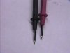
Yeah, and I feel like an idiot for not at LEAST wrapping the probe with electric tape.:tears:
I wonder if Radio Shack carry those covers.:scratch2:

Two pieces of heat shrink tubing will work.
 

Attachments

  • 140F07-5-26(20-0).jpg
    140F07-5-26(20-0).jpg
    32.3 KB · Views: 14
markthefixer said:
Ok, a quick sitrep of which transistors are in, and which positions are empty
is needed
BEFORE turning anything on....

My expectation is :
Q1, Q3, Q5, Q7, Q9, Q11, D5 and C4 are installed , which lets us check that the +52v and +32v regulators are working.

and that Q2, Q4, Q6( the incoming (2s)k34 jfet), Q8, Q10 and Q12 are NOT installed...


once the +32 and +52 are ok

then Q2, Q4, Q6( the incoming (2s)k34 jfet) and Q8 are installed for the -52v regulator.

once the -52 is ok

then Q10 and Q12 are installed for the -32v regulator.


I trust Q6 is ok? I only have 1 of these K34 fets.
Also was any of the lytic caps replaced on the board?
 
There are two 2sk34 fets in the unit, Q5 for the +52 and Q6 for the -52 .

markthefixer said:
We used a NTE 459 (as a 2sk34 replacement)on the positive sides Q5...

The incoming k34 will be used in the Q6 position, in the -52v regulator.

We should have gotten two, but hadn't progressed that far to know it was bad...

The C4 electrolytic across the 6v zener was replaced, just in case...
 
Well it seems I jumped the gun a bit....I installed ALL of them including Q2, Q4, Q8, Q10 and Q12. I thought I'd be saving time by having everything intalled by the time Q6 arrives.....that's it....the next time I will wait on your instruction before getting too ahead of ourselves.....I haven't turned anything on though so we're ok there at least. I can go ahead and pull back out Q2, Q4, Q8, Q10 and Q12.
 
Back
Top Bottom