• The move to the new server is done. There are some software and database maintenance updates in process. This has us passing the hat around to help out. We appreciate any donations. Seriously, even a dollar helps. The payment page may be found here - https://www.audiokarma.org/support.html

Sansui AU-6900 Woes .......

is the "formal" DC Offset measured between ground and those emitter resistors?
No, this measurement is taken by inserting the black probe to your negative speaker output, and the red probe to the positive speaker output, readings in mV. Obviously it wont work if the relay isnt clicking the speakers "on."

The one thing about the measurement on the emitter resistors, when I turn the amp on its about 15V then eventually after 20 mins or so it slowly leaks to below 8V. (not sure if that's normal)
Are you getting readings in VOLTS or MILLIVOLTS. It really needs to be millivolts, or we have a serious problem here!
 
Good morning!

The DC offset I have not measured in some time. I will advise.

The "voltages" discussed are from chassis ground to the 8 large ceramic R59-R70.
 
Ignore the dc offset comment above, not much good measuring if relay circuit not working!

Yes those measurements mentioned above are in V not mv.
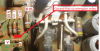
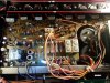
I will upload a pic.
 
FWIW you can energized the relay (assuming the protect circuit components are good) by grounding base of TR601. Jumper leads, and do it with no power unless you are a risk taker. . NO SPEAKERS OR LOAD CONNECTED. It will verify that the rest of the protect circuit is okay, and will give you DC on the speaker outputs. (but speaker selector has to be on) Once satisfied, do yourself a favor and disconnect the ground.
upload_2017-10-2_21-19-2.png

. I would start by verifying plus and minus voltages, then start measuring voltages around the input pair and first transistor. (trouble shoot one channel.)
The quick way to verify the supply voltages is to measure the collectors of the output transistors. This is the metal case. The PNP will have minus supply voltage, and the NPN will have positive supply voltage.
Then check the filtered voltages They are the voltages which go through resistors R31, R32, (around +42 volts) and R41 and R42. (around - 42 volts. ) I say around, as they are filtered, not regulated, and there is a couple volts drop across each one. These voltages come from TR604 and TR605, through some 47 ohm resistors. After thinking about it, it is very possible that your problem is in this area.
 
Hi Steve,

In regards to your message about energizing the relay;

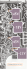
TR601 is not in the image you have marked up. TR601 is just to the left (off the screen) of the that diode that is just left of the 180kohm "33v" resistor.

Assuming that it is the true TR601, am i de-soldering the base and connecting to ground or simply inline connecting the base of that tr to ground?

I hate to ask a rookie question here but from all threads above I can i make some assumptions:

  1. That the voltages across the emitter resistors should be in mv not volts thus something is way out of wack if I'm getting like 6-7v ???? (which I am)
  2. The two channels should be pretty similar in voltage readings pretty much all the way through the circuit? (assuming the same point measured between L & R channels)
  3. To expedite, using the process of elimination (I completely understand and have learned that just replacing components is a very,very bad troubleshooting technique) however, I have really only a few components on the PA board that have not been replaced:
  • The two A798 5pin transitors
  • The zener diodes
  • The large diodes SS-5 and SS-5R
  • The filter coils
  • Some resistors
  • Most of the smaller ceramic capacitors
  • The two bias pots
Could any of the components above represent the potential issue I am having?

In regards to the requested voltages (btw these four resistors have been replaced)

Assuming R41, R31, R42, R32, voltages are as shown.

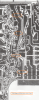
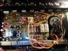
upload_2017-10-2_22-0-37.png
 
1 the point indicated also goes to base of 601 and to one side of C604. I picked the end of those resistors as seemed easiest place to clip ground lead, but this is secondary.

The -17 and -23 voltages should both be around -45. Go back to TR604 and R604.(47 ohm resistor) and measure voltages. Most likely the resistor is bad (when resistors go bad, they usually either go open or increase. It's possible (not as likely) that the filter cap C606 could be open, causing low voltage on collector of TR604. If collector voltage is okay, suspect tr604 or problem with C607 (no likely but...). Also, another aid - nearly all Japanese transistors (including all the ones in this amplifier) the collector is the center lead.

upload_2017-10-4_7-49-10.png
 
Last edited:
Readings:

TR604 Collector (center pin) = -49.5V (+-.5v)

R604 = -44V & -38V (BTW replaced R604)

C608 = -38V

Fun facts:

C604 - I originally had replaced that cap with a regular 100uf 6.3V cap. After reading thread a few back, I put the original BP cap back in, so it is old.

R605, TR602, D611 am literally getting like 13mv.

The readings across the bank of diodes are:

D608 = -50V
D606 = 52V
D607 = -50V
D605 = 52V
D604 = 46.75V
D603 = 46.75V

Also

D613 = 45.6V on both sides of the diode

Also also

lch = approx 6V
rch = 7.5 to 7.8V

Measured at the resistors you showed in your pic from Monday at 6:53pm

Thanks again for your patience and persistence.
 
OK big update to above post.

I'm learning .....

I looked more carefully at the circuit, specifically, TR601 thru 604.

I discovered that I had them, along with several other (replaced) transistors in BACKWARDS. (I also inspected all the replaced Tr's for correct E/B orientation)

I removed and reconnected those properly and retested.

Note: Protection circuit is still not clicking off.

All 8 emitter resistors now measure:

=9.95V

lch = 9.9v
rch = 9.9v

r604 = -47v

tr604 = -51v

C608 = -40V
 
Until you get the output voltages sorted out, the protection circuit will not engage. (or are you testing protector with base of 601 grounded?)

Based on voltage on r504 and c608, TR604 should be good, but amplifier circuit is drawing more current through r604 and the 220 ohm resistors (negative supply to amplifier). Verify the voltages on the output devices (the case of the outputs is the collector, which is the supply voltage.)

Sanity check with small Japanese transistors. Collector is normally center lead. They should only read one direction with diode test, to the base lead. I usually but a small bend in the base lead after I identify it, just to keep my leads straight. Diode test on DMM - NPN negative DMM lead on the collector, positive will conduct on the base. 0pposite for PNP.

 
Referring to the indication of +12V on the 220ohm resistors. It looks like TR605 the +40V regulator either isn't working or it is being pulled down by excessive current draw or failed components, Check and ensure you have correct power supply voltages first - always.
 
After replacing (1) TR605 and TR604 the resistors (2) R42 and (3) R28 burn out after a few seconds on power up.

Thoughts?

Thanks

Cam

20171014_125939.jpg
 
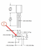
I have found the while most transistors have the collector as the middle pin, some have the E & B reversed from others.

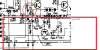
I just want to make sure i'm reading these diagrams right, is the emitter in the image below correct?

GBC-ASUSGAMER 10-14-2017 6.12.44 PM.png
 
Ok, so after resolving and checking all transistors for correct orientation (Thanks Fuxtor) I now have more appropriate voltages across the 220ohm resistors.

They are now basically -41 or 48v in pairs.

However TR04 which I replaced with an NTE382 is super hot, cannot touch it which cant be right. (Was a 2SC1951)

Still no luck on protection circuit.

Thanks

Cam
 
Back
Top Bottom