

You are using an out of date browser. It may not display this or other websites correctly.
You should upgrade or use an alternative browser.
You should upgrade or use an alternative browser.
Sansui Eight help - hum on one channel
- Thread starter KeithD
- Start date
-
- Tags
- sansui eight

Sorry for confusing you.
TR857
TR859
TR856
TR860
Well, surprisingly it doesn't look like you have 'lost' any OP transistors. However, we again have the same DC offset issue which appeared to resolve itself by removing F005 & F006, so I would hesitate to say that the cause is blown driver transistors (as you didn't short both channels with your meter). And we also know that you can't get the bias to adjust low enough for spec' which is 8-10mA according to the SM I have - this seems quite low to me, as the bias current measured is the current for all six transistors of the output stage of the driver board plus OP transistors.
At the moment I am thinking there may be an intermittent connection on one of the negative supplies to the driver board & OP transistors. And the mechanical stress caused by the removal of F005 and F006 fixed it for a while, and then un-fixed itself while you were adjusting the bias.
I think it's time to pull the plug on this one - I think I've given it a fair shot. The lack of the correct main board diagram, consistent component numbering on the schematics we have, and the fact that I have never worked on one of these. All are in the mix to cause both of us problems too significant to resolve via this medium I think.
I have the OP transistors on the schematic listed as - from top to bottom:-Did you mean TR857 and 858? Will check those.
TR857
TR859
TR856
TR860
Well, surprisingly it doesn't look like you have 'lost' any OP transistors. However, we again have the same DC offset issue which appeared to resolve itself by removing F005 & F006, so I would hesitate to say that the cause is blown driver transistors (as you didn't short both channels with your meter). And we also know that you can't get the bias to adjust low enough for spec' which is 8-10mA according to the SM I have - this seems quite low to me, as the bias current measured is the current for all six transistors of the output stage of the driver board plus OP transistors.
At the moment I am thinking there may be an intermittent connection on one of the negative supplies to the driver board & OP transistors. And the mechanical stress caused by the removal of F005 and F006 fixed it for a while, and then un-fixed itself while you were adjusting the bias.
I think it's time to pull the plug on this one - I think I've given it a fair shot. The lack of the correct main board diagram, consistent component numbering on the schematics we have, and the fact that I have never worked on one of these. All are in the mix to cause both of us problems too significant to resolve via this medium I think.
Last edited:

Yes, schematic seems to have some typos. There are two transistors listed as TR856. I'm pretty sure the one connected to B8 should be TR858.
Thanks for all your help. I understand. When you can't trace down a problem it gets very frustrating and seems like it is going on forever.
No idea what happened pulling F005 and F006 to make 8H go to zero volts.
If I can't track the problem down, the decision will be whether to send this out for restoration, which will likely be in the $600+ range, or sell it to someone who wants to take it on.
Thanks for all your help. I understand. When you can't trace down a problem it gets very frustrating and seems like it is going on forever.
No idea what happened pulling F005 and F006 to make 8H go to zero volts.
If I can't track the problem down, the decision will be whether to send this out for restoration, which will likely be in the $600+ range, or sell it to someone who wants to take it on.
Well done for checking the other transistors (you're getting used to it I think  ) - they look ok.
See what you can find regarding an intermittent connection, actually it could be anywhere, but as it does it to both driver boards, it rather suggests 'power supply'.
Lastly the fault looks fairly benign at the moment, don't be tempted to put it on 'full mains' until you can at least get 0V DC offset consistently. Getting the bias to function correctly is also a potentially 'dangerous' procedure - really also needs DBT use with this unit's history.
) - they look ok.See what you can find regarding an intermittent connection, actually it could be anywhere, but as it does it to both driver boards, it rather suggests 'power supply'.
Lastly the fault looks fairly benign at the moment, don't be tempted to put it on 'full mains' until you can at least get 0V DC offset consistently. Getting the bias to function correctly is also a potentially 'dangerous' procedure - really also needs DBT use with this unit's history.
Last edited:
Thanks for the advice, John. I did check ground points on both the driver boards and PS board. Not seeing anything amiss there.
It's possible with all the moving around that a solder joint cracked on the PS board. That one is a bit trickier to get at, but might be a good idea to check those and/or reflow solder joints - especially on the circuit for B3 and B4. Might also be a bad cap or transistor on those circuits. Checking those will be the next step, but if I get to the point of pulling e-caps, I might as well replace them. I don't have any of those on hand, so will need to order.
That brings me to the critical juncture: spend more time/money on this unit hoping to get it working, send it out for rehab, or cut losses and move on. If I were to send it out, would most likely send it to QRXRestore as the Sansui experts. Restoration is $575. When I add shipping and what I paid for the unit, I'll be close to $800. Don't know if I could ever get that money out of it. So, that route seems to be cost prohibitive. Checked with one shop in Minneapolis area, which is not far from me, but they don't work on Sansui. Probably best to put a bit more time/effort in to this working on the PS board and get new OTs. I'd probably be at $40 in parts with the OTs, recap drivers and PS. Should also get transistor replacements for PS on the same order just in case.
Anyone aware of replacement parts list for the Eight? I'll do some searching to see what I can find. Anyone know of a reputable tech for Sansui in Minneapolis, Madison, Milwaukee area?
It's possible with all the moving around that a solder joint cracked on the PS board. That one is a bit trickier to get at, but might be a good idea to check those and/or reflow solder joints - especially on the circuit for B3 and B4. Might also be a bad cap or transistor on those circuits. Checking those will be the next step, but if I get to the point of pulling e-caps, I might as well replace them. I don't have any of those on hand, so will need to order.
That brings me to the critical juncture: spend more time/money on this unit hoping to get it working, send it out for rehab, or cut losses and move on. If I were to send it out, would most likely send it to QRXRestore as the Sansui experts. Restoration is $575. When I add shipping and what I paid for the unit, I'll be close to $800. Don't know if I could ever get that money out of it. So, that route seems to be cost prohibitive. Checked with one shop in Minneapolis area, which is not far from me, but they don't work on Sansui. Probably best to put a bit more time/effort in to this working on the PS board and get new OTs. I'd probably be at $40 in parts with the OTs, recap drivers and PS. Should also get transistor replacements for PS on the same order just in case.
Anyone aware of replacement parts list for the Eight? I'll do some searching to see what I can find. Anyone know of a reputable tech for Sansui in Minneapolis, Madison, Milwaukee area?

stereofun
Super Member
I'd absolutely just replace parts. Kind of press the Control / Alt / Delete - button. Maybe step away for a bit. Then come back and build a cap list - finish a board at a time, have fun with in - learn - get new OT's in there for sure. It is worth the investment in time and will be quiet valuable too once restored, and it will sound much sweeter because you did it yourself - as a bonus you will come out so much stronger, that vintage problems in the future wont bug you down, if you can restore an Eight - you are good, its not an easy amp to content with.
I'd absolutely just replace parts. Kind of press the Control / Alt / Delete - button. Maybe step away for a bit. Then come back and build a cap list - finish a board at a time, have fun with in - learn - get new OT's in there for sure. It is worth the investment in time and will be quiet valuable too once restored, and it will sound much sweeter because you did it yourself - as a bonus you will come out so much stronger, that vintage problems in the future wont bug you down, if you can restore an Eight - you are good, its not an easy amp to content with.
Thanks for the encouragement, Tom. Did flow the solder on some of the easier joints to get to on the PS board. No change in condition. But, while monitoring DC offset I used a wood chopstick and just touched some of the caps and transistors to move them slightly looking for a bad joint. Not sure which component it was now, but when I touched something on the tone control board (F-1235), I got big movement on the offset and seemed to settle out at around -0.7 V. Eventually, I ended up at 37 V again, so I think there may be a bad joint somewhere. Also noticed that DC offset does change with the selector switch. I get the lowest value with the tuner selected, then Phono, then AUX is highest. Variation is about 2 V.
I agree this one is worth keeping and bringing back. All the stuff I read is how much people love the Eight. It's the only reason I picked one up. I would be ok changing caps and bad transistors, but I am not expert enough to know which replacements are best for each position/board. I'm not seeing a BOM for the Eight with recommended replacements. When I spent time on Pioneers over in that forum, there are vetted BOMs for many of the popular receivers/amps. Not seeing anything like that for the Eight. I know what OTs to get and likely can figure out the replacement trimmers for the driver boards. With Pioneer gear, Nichicon UPW and UKL seem to be preferred replacement e-caps, Wima and KMET for film caps, but they are application dependent, and I would not know what is appropriate where. So, without at least general guidelines for what to use on each board, I'd be taking guesses. I can read from the SM the rating of the e-caps, but would really want to draw on the experience of others for appropriate replacements.
Tone control board looks like it might be a good place to start. All the wire connectors can be documented for location/connection point and pulled off (no soldering needed). Driver boards only have two e-caps each, so that's easy to do with correct replacements. PS should be done, but that one is more difficult as all connection wires will need to be clearly documented and then de-soldered.
Does anyone have a BOM they can share for restoration work on the Eight?
I just found this in one of @stereofun 's posts, (thanks Tom  ) you'll find this highly instructive when you get that fault fixed.
https://audiokarma.org/forums/index.php?threads/eight-driver-board-adjustments.707373/#post-9493418
) you'll find this highly instructive when you get that fault fixed. https://audiokarma.org/forums/index.php?threads/eight-driver-board-adjustments.707373/#post-9493418
+1With all the credit to the late great Jim, founder of qrxrestore.com AK Trnsfrmr
Absolutely, I forgot myself for a moment there.
A few days ago I separated pre-amp from amp and measured DC offset. Still at 37 V, so I think the issue clearly is in the amp section.
Tried a few things yesterday. First pulled L side OTs, then measured DC offset. Still got 35-37V.
Pulled R side OTs, still got 35-37V.
Pulled driver boards and DC offset (measured at speaker outputs) was at about 0.2V
Put one driver board back in, and offset back to 35V on that side.
Left driver boards out and put OTs back in one side at a time (checked to make sure they were not shorted to ground). Offset was same as without driver boards, about 0.2V.
Put one driver board in (tested both channels) and offset goes back to 35-37V. Tried the same with other driver board and same results.
Does this point to the problem really being on the driver boards? I'm sure it's possible something fried on both boards when I had the shorted OT.
Or, is this pointing to something else feeding both driver boards, such as the power supply?
I think I will try these tests with F005 and F006 out to isolate the amplifier section from the speaker protection board.
Tried a few things yesterday. First pulled L side OTs, then measured DC offset. Still got 35-37V.
Pulled R side OTs, still got 35-37V.
Pulled driver boards and DC offset (measured at speaker outputs) was at about 0.2V
Put one driver board back in, and offset back to 35V on that side.
Left driver boards out and put OTs back in one side at a time (checked to make sure they were not shorted to ground). Offset was same as without driver boards, about 0.2V.
Put one driver board in (tested both channels) and offset goes back to 35-37V. Tried the same with other driver board and same results.
Does this point to the problem really being on the driver boards? I'm sure it's possible something fried on both boards when I had the shorted OT.
Or, is this pointing to something else feeding both driver boards, such as the power supply?
I think I will try these tests with F005 and F006 out to isolate the amplifier section from the speaker protection board.
Good idea, this is what seemed to make the DC offset controllable before - for a while at least - then it all went pear-shaped again.I think I will try these tests with F005 and F006 out to isolate the amplifier section from the speaker protection board.

Pulled F005 and 006 and measured DC offset. R channel is at 0.3V, but l channel is at -24V. So, having F006 in for the L channel was pulling the voltage down, which seems like it could be a bad ground in the amp section?
With the driver boards in and F005, 006 out I was still getting 37V offset.
I think next will be to check TR853 and TR855.
With the driver boards in and F005, 006 out I was still getting 37V offset.
I think next will be to check TR853 and TR855.
Last edited:
After reviewing the schematic, SM locations, and those two transistors in the unit, I believe TR853 and TR855 were in the wrong locations. Put them in the correct locations according to SM (should be mirror image of R channel locations, TR853 toward the front (2SC680) and TR855 toward the back (2SA566)). Ok with no driver boards. With both boards in DBT stays lit. Pulled L driver board, DBT goes dim, DC offset 37V on R channel, L channel DC at 10V. Tried both driver boards in R side with same result.
So, seems like driver boards are NOT the problem, but rather when a driver board is in the L position, it is completing a shorted circuit. Does that sound correct? Any ideas here? I did pull TR853 and 855 and diode check, both OK. Really seems like there is a L channel problem that is affecting both channels?
So, seems like driver boards are NOT the problem, but rather when a driver board is in the L position, it is completing a shorted circuit. Does that sound correct? Any ideas here? I did pull TR853 and 855 and diode check, both OK. Really seems like there is a L channel problem that is affecting both channels?
stereofun
Super Member
Forgot to mention that I did pull TR853-860 and did diode check for shorts. Then put each one back in. I did the test you suggested with the TRs in place and no shorts to ground on any of those TRs.
I think you are unto to something with your last post #136 - I re-read the tread and saw the quoted post here from pretty early on. This is where the compounded troubles began I think - where you went from a bad left channel to the mystery of having both channels show high DC regardless of which driver board in which slot. We were all scrambling our heads trying to understand a common source that could take out both channels - but what happened was that when you pulled all the drivers you got them back in wrong. You see you cant put one transistors in wrong of this casing because of the pin spacing, and with regard to the Outputs its not a problem to shuffle them, since they are all NPN, but the drivers TR853/855 & TR854/856 are paired as NPN/PNP and THOSE can as you mention be put in wrong, not individually, but as a config LEFT TO RIGHT
So this was your common fault - even if you pulled them out again later and "re-tested" them to be fine, they would still act up with the high DC once re-inserted wrongly.
Now first thing first. Scroll down to the SM manual "Other parts and their position on chassis" and check not only TR853/855 but also the other sides TR854/856 - with your transistor tester you can verify that
TR853 LEFT CHANNEL (closest to the front panel) is an NPN 2SC680
TR855 LEFT CHANNEL (closest to the back)panel) is a PNP 2SA566
TR854 RIGHT ----"---- (closest to the front panel) is an NPN 2SC680
TR856 RIGHT ----"---- (closest to the back) panel) is a PNP 2SA566
Yes, TR853-856 are now in the correct positions matching the SM. I don't know when these were switched, but I usually pay close attention to put the transistors back in the positions I found them. Assuming the receiver would not have worked with them swapped on the L channel, then I must have mistakenly switched them at some point. I know I did not consult the SM to confirm their positions until yesterday. When I compared SM, I found R channel transistor positions matched SM, but L channel ones did not. Triple checked the two plus schematic to make sure there was not an SM error. So, after making sure TR853-856 were in the correct positions, I'm at the situation I described with DBT not going dim when a driver board is in position on the L channel.
I have not re-checked parts on the L channel circuit but not on the driver boards:
R851 and R853 (another mistake on schematic, which lists this as R835 - resistor on emitter of TR859).
TR851.
I have not re-checked parts on the L channel circuit but not on the driver boards:
R851 and R853 (another mistake on schematic, which lists this as R835 - resistor on emitter of TR859).
TR851.
stereofun
Super Member
...so back to square one eh? - That was the only common source I could think of. I have replaced those exact drivers in both my Eight and 999 with modern TO220's - and both times I remembered how careful you had to be to get the right "type" in the right slot. Then reading through your post and seeing you had pulled them at least ones, made sense. So we know the left side drivers were wrongly inserted, but seemingly not the right side. If at some time both sides had been in the wrong positions, it would be conceivable that while the drivers survived (as testing shows), something around them didn't - which could explain the two sides acting in uniform. A beauty of this symmetrical design is that it is usually just one side that goes bad, then by swapping boards or playing around with the pre to main (crossing connecting cables) you can fairly quickly determine LEFT vs RIGHT PRE-AMP vs MAIN-AMP.
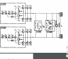
Now at some point you mentioned DC correcting itself when a board was moved. I had a situation with my Eight when the top and back plate were off - moving the beast around, especially if you lift it primarily in one corner, can produce enough torque/twist in the chassis to momentarily loose signal, that I saw first hand. While not a likely scenario, you can try to have both driver boards in, with the DC probes in and see if creating torque as described corrects either side.
On a separate note I think we can assume that the protector block is not doing its job - with the boards in it should never allow 37V on the terminals. If you look at a block diagram you will see that the protector block and the F-1202 are common links between the two channels, it would not make sense to me that a fault here could cause the problems here since they are separated by fuses (do make sure they are quick acting) - but sometimes its good to take a look from above so to speak.
Now at some point you mentioned DC correcting itself when a board was moved. I had a situation with my Eight when the top and back plate were off - moving the beast around, especially if you lift it primarily in one corner, can produce enough torque/twist in the chassis to momentarily loose signal, that I saw first hand. While not a likely scenario, you can try to have both driver boards in, with the DC probes in and see if creating torque as described corrects either side.
On a separate note I think we can assume that the protector block is not doing its job - with the boards in it should never allow 37V on the terminals. If you look at a block diagram you will see that the protector block and the F-1202 are common links between the two channels, it would not make sense to me that a fault here could cause the problems here since they are separated by fuses (do make sure they are quick acting) - but sometimes its good to take a look from above so to speak.
Decided I needed to check the actual wiring underneath to confirm TR853 is toward the front and TR855 is toward the back (L channel). When I checked which pin on the L side driver board ECB of TR853 and TR855 are connected to, it appears the SM is in error. The driver boards are mounted with the foil side facing the interior of the receiver and printed side facing out. They can't be put in backwards as they do not fit. Thus the pin designations from left to right are set.
According to the schematic:
TR853 (2SC680) ECB connects to driver board pins KLM
TR855 (2SA566) ECB connects to driver board pins IFD
Looking at the wiring in my unit, this can only be the case if TR853 is mounted toward the back and TR855 is mounted toward the front, which is the way I had them in. Now, with them put in place the way the SM designates, DBT stays bright with the driver board in place. When I had the transistors the way the schematic designates (TR853 and 855 swapped), DBT would dim. So, I believe my original configuration (which I believe is how TR853 and 855 were in there from the start) is correct and matches the schematic for where the connections need to be.
Can anyone confirm this on their Eight?
According to the schematic:
TR853 (2SC680) ECB connects to driver board pins KLM
TR855 (2SA566) ECB connects to driver board pins IFD
Looking at the wiring in my unit, this can only be the case if TR853 is mounted toward the back and TR855 is mounted toward the front, which is the way I had them in. Now, with them put in place the way the SM designates, DBT stays bright with the driver board in place. When I had the transistors the way the schematic designates (TR853 and 855 swapped), DBT would dim. So, I believe my original configuration (which I believe is how TR853 and 855 were in there from the start) is correct and matches the schematic for where the connections need to be.
Can anyone confirm this on their Eight?