• The move to the new server is done. There are some software and database maintenance updates in process. This has us passing the hat around to help out. We appreciate any donations. Seriously, even a dollar helps. The payment page may be found here - https://www.audiokarma.org/support.html

Sansui Eight help - hum on one channel

Placed parts order on the weekend. Ordered most of the stuff from Mouser, but they were out of stock on one of the driver transistors. No delivery until September, so I order those from Digigkey along with the mica spacers. Hopefully, I will be back at this by the weekend!
 
Parts came in yesterday and I replaced 4 output transistors and 4 drivers. Checked for shorts, and powered on DBT. OK so far. Amp/pre-amp separated, output fuses removed. Measured L and R driver board pin voltages:

Pin, L, R
P, 49.9, 50.2
O, 0, 0
N, 0, 0
M, 0, 0
L, 0, 0
K, 0, 0
J, 41.5, 41.2
I, -0.7, -1.1
H, 0.5, 0.14
F, -40.8, -40.9
E, -41.2, -41.3
D, -0.01, -0.01
C, 0, 0
B, -48.7, -48.7
G, 0, 0
A, 0, 0

Much better and consistent from L to R channel compared to what I had with the old transistors.

Decided to put driver boards in and check DC offset: 37V on both channels! :mad:

So.... still have the offset problem. Driver pin voltages are much better, so that is an improvement. Still concerned that with no driver boards in I am getting 0.5 and 0.14 V at pin H. Shouldn't those be zero?

Replaced the two e-caps on both driver boards, and TR801 and 802. Next will be trimmers.

After that I am again at a loss for where to look next.
 
Replaced the trimmers on one driver board and tried that in both L and R channels. Still getting 37V at the speaker outputs on both channels. I also disconnected F-1334, but this did not affect the high DC output.

I'm starting to wonder if this is a power supply issue since both sides are affected. Pulled F001-4, so no B8 or 9 power to the driver boards or driver and output transistors. Measured DC offset at both speakers: 27.5V. I don't know what B8 or 9 are supposed to be, but wondered if they were getting too much power. Here again, with zero volts input to the driver boards, I would expect zero out.

B3 (pin P) is high. It should be 46.5 V according to schematic, but I'm getting 50V there. Also, B5 (pin B) is also high (-48.7V). It should be -46.5V per schematic. I really have no idea if this is just a PS issue, or something happening equally to both driver boards.

Next up is recapping the PS board. I ordered all the replacement caps Nichicon UPW series. With snipping a couple of the cable bundle ties and disconnecting one or two ground wires, looks like I should be able to swing that board up and around to access all the solder points.

Anyone think the high DC offset may be caused by a problem on the PS? If the recap does not help, I'd have to look at the PS transistors. I'm not familiar with the ones used on this PS, so I'd be looking for the suggested replacements.
 
Tried one more thing. Pulled driver boards with F001-4 out. Getting about 30mV at speaker out.
 
Tried one more thing. Pulled driver boards with F001-4 out. Getting about 30mV at speaker out.
That is 'as expected', because removing those fuses removes the source of the ~27 or so volts on the output. Note that if the DC offset is positive - the positive half of the power amp is turned on hard, so the amplifier is unable to 'balance' itself for some reason. The power supply voltages you noted as high, might be caused by damaged components in the PSU, but could possibly be due to slightly high mains voltage at your location.

As for transistors
2SC486 = KSC2690
2SA486 = KSA1220 (after shortages, Mouser has over 1000 in stock now).
C8003-1 = KSC2690
2SC632A = KSC1815
2SD223 = KSC5603

You said something about 2SC486 & 2SA486 not being the transistors in your unit? or the schematic being wrong? - please let me know what you have in there, then I can revisit the above list and revise as necessary. (I can also add Mouser links if you need them).

 
Last edited:
That is 'as expected', because removing those fuses removes the source of the ~27 or so volts on the output. Note that if the DC offset is positive - the positive half of the power amp is turned on hard, so the amplifier is unable to 'balance' itself for some reason. The power supply voltages you noted as high, might be caused by damaged components in the PSU, but could possibly be due to slightly high mains voltage at your location.

As for transistors
2SC486 = KSC2690
2SA486 = KSA1220 (after shortages, Mouser has over 1000 in stock now).
C8003-1 = KSC2690
2SC632A = KSC1815
2SD223 = KSC5603

You said something about 2SC486 & 2SA486 not being the transistors in your unit? or the schematic being wrong? - please let me know what you have in there, then I can revisit the above list and revise as necessary. (I can also add Mouser links if you need them).
Thanks for that insight on the voltages, John. B3 and B4 are a bit higher after putting in the new OT and driver transistors, so I was just thinking this might be more of a PS issue since both channels are affected equally. I am also concerned about 0.2 to 0.5 V at H (signal output from driver boards) with no input (pre out/main in separated). So, wondered what was amplifying what should be a 0V signal?

Thanks for the subs on on the PS transistors. I believe I have 2690 and 1220 on hand. I am away from home at the moment, and will check what is on the board this weekend.

My next test (in my mind) is to remove B8 and 9 (I don’t know what they should be) from drivers and see what DC offset is. Just thinking about narrowing down if one of the PS voltages is causing the high offset issue.

Then, planning to recap PS this weekend. I suspect several of the caps are out of spec just by the looks of them, but will test each one as I pull them out.
 
Thanks for that insight on the voltages, John. B3 and B4 are a bit higher after putting in the new OT and driver transistors, so I was just thinking this might be more of a PS issue since both channels are affected equally. I am also concerned about 0.2 to 0.5 V at H (signal output from driver boards) with no input (pre out/main in separated). So, wondered what was amplifying what should be a 0V signal?
The B3 & B4 voltages should be 'regulated' to some extent, you should see a difference between the collector and emitter voltages of each of the 'pass' transistors (2SA486/2SC486). There are no zeners in that part of the circuit as the 'regulators' are 'capacitance multiplier' style regulators which remove ripple but don't do much regarding 'fixing' (or regulating) the output voltage, as it would if a zener or two were used.

My next test (in my mind) is to remove B8 and 9 (I don’t know what they should be) from drivers and see what DC offset is. Just thinking about narrowing down if one of the PS voltages is causing the high offset issue.
I would think they will rise slightly 'off load' it doesn't seem like there is much current flowing, so I am guessing 1 or 2 volts increase at the most.
Then, planning to recap PS this weekend. I suspect several of the caps are out of spec just by the looks of them, but will test each one as I pull them out.
Ok, I'll be looking out for anything more you have to post on this, as I am keen to support you as much as I can.

My goodness how I would love to get your Eight on my bench here. :angel:
 
Last edited:
I am keeping an eye on this thread while on vacation in Denmark. Its such a mystery what's going on, but fascinating to watch the development.

KeithD, you are in the best of hands and you and John will get this sorted and the rest of us will learn a thing or two :thumbsup:
 
Thanks again for all the help John and the encouragement, Tom.

Checked PS transistors, TR005 is 2SC486, but TR006 is 2SA486. This is correct on the schematic, but incorrect in the SM.

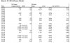
Pulled all e-caps on the PS board today and measured capacitance and esr for each. Here are the results:

Sansui Eight PS cap values.jpg

Almost all were over their spec, C011 being the worst. Voltages in parentheses are what was actually on the board. I ordered 16V cap for C011. However, I ordered what the SM had for the 1000 µF caps (6.3V). Hopefully this is not a big issue.

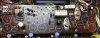
Here is a picture of the board sans e-caps:

Sansui Eight PS.JPG

Any transistors or other parts I should check or replace while I am in there before putting the new caps in?
 
Any transistors or other parts I should check or replace while I am in there before putting the new caps in?
Just a vague thought that the black and white transistor TR003 (although smaller) looks like those unreliable (noisy) 'flying saucer' transistors found in other Sansui gear which get changed straight away. (possible replacement listed in post #166 - but in this location a KSC1815 would also be fine).

Other than that, usual stuff, check the voltages across any zener diodes, check that there is a difference between the collector and emitter voltage of the 'series pass' transistors. Remember this is a PSU, first power up after all this work should be on DBT, just to make sure it powers up without any drama. :)

Your chart of capacitance spec's shows the tendency for caps past their best to markedly increase in value, so what you are doing is definitely worthwhile. ;)
 
OK, thanks. I do have KSC2690 on hand for TR003 and TR005. I also have KSA1220 for TR006. I do not have KSC1815 or KSC5603. Might do the recap first and see what happens on DBT before starting to replace transistors. Since TR005 and 006 connect to B3 and B4, might be worthwhile replacing them anyway and see if the voltage comes down. I think you suggested that while back.
 
Finished the PS recap.

Sansui 8 PS recapped.JPG

Checked voltage across Zener diodes:

ZD001: 14.0V
ZD002: 23.7V

Getting about +41V DC offset with driver boards in.
 
Hey guys, been following this thread as I just got myself an eight also.
If you don’t mind a suggestion, you should stop changing parts and try to find the problem with the driver board first. Work with just one driver board and Leave the other one out in till you get that one working.
Another suggestion is to pull out the output transistors and check the driver board with Them out. It should have correct voltages ie 0 volts at the speaker output. BUT if you try this do not hook any speakers up and keep the volume control all the way down. The driver card can not supply any power with the output transistors removed and may smoke if you turn the volume up.
I also have the version without the relay and looks like it is all original and working. I do not have the correct schematic for (have a very poor copy) this version.
 
Another suggestion is to pull out the output transistors and check the driver board with Them out. It should have correct voltages ie 0 volts at the speaker output. BUT if you try this do not hook any speakers up and keep the volume control all the way down.
Already did that and posted the results in post #133.

The mystery to me is that both channels are at (now) 41V DC offset with both driver boards and all OT in. So, what could be affecting both sides equally?
 
If this were on my bench, I would pull all output transistors and all driver transistors, then put all fuses in and one driver board in and check output voltage, + and - voltages feeding output transistors (b8 and b9) and + and - voltages feeding the driver board(b3 and b4). Keep this on the dbt until all issues are found. You could leave the output speaker fuses out if you still suspect the protector board is fishy.
In this configuration with all power supply voltages correct, this should narrow the problem down.
Also, verified on my unit, the pnp driver transistor sits under the input capacitor of the driver board, front on one side and rear on the other.
Also have you checked r836 the 15 ohm resistor on the driver board?
 
B3 (46.5V) and B4 (-46.5V) are marked on the schematic, and with the driver boards pulled I am getting 50V for B3 and -48.6V for B4. Both clearly too hight.

What should B8 and B9 be? At one point I measured all the voltages at the connections on the PS with the driver boards out. B8 was 40.7V, and B9 was -40.8V. I have not measured those voltages will the OT and driver transistors out.
 
I do not have the correct schematic for (have a very poor copy) this version.
By the way, I downloaded the schematic from HiFi engine. If I can figure out how to upload a pdf file, I'll post my copy that I have corrected several mistakes.
 
The main filter capacitors are 50 volt caps according to the schematic. That seems a little close for me. What is your line voltage selector set at? It might just be because we are not pulling any current. The b8 and b9 are probably ok. What is your output voltage at the driver board. Don’t leave it on longer than required to measure the voltages. That is right at the voltage rating for this big caps.
 
Back
Top Bottom