• The move to the new server is done. There are some software and database maintenance updates in process. This has us passing the hat around to help out. We appreciate any donations. Seriously, even a dollar helps. The payment page may be found here - https://www.audiokarma.org/support.html

Sansui relay subs

Has there always been a time limit on editing ? I can no longer edit the first post of this thread.

So updating below - adding AU-217

-------------------------------
Sansui 8080: MY4-02-DC24
Sansui 9090: MY4-02-DC24
Sansui 9090db: MY3-02-DC24

Sansui AU-217: Speaker relay --> MY4-02 DC24
Sansui AU-517: MY2-02-DC24
Sansui AU-717: Taiko RABK 2B --> MY4-02-DC24

Sansui AU-9900 / 9900A: Omron #MY4-02-DC24
Sansui AU-11000: Omron #MY4-02-DC24
Sansui AU-20000: LY2-0-DC24 (x1); MY4-02-DC24 (x1)

Sansui AU-X1: LY2-02-DC24 (speaker x2); ? (Soft Start x1); G5V-2 24DC (Signal x5; need leg extensions); 24V DC reed relay --> Omron G5V-2 24VDC (Headphone 1x - not direct drop-in but easy job)

Sansui BA-F1: MY4-02-DC24 (speaker x2; cut off 'NC' pins x4 as no holes in PCB for them).

Sansui G-4700: none
Sansui G-5700: 1150400 or 480 --> MY4-02-DC24
Sansui G-6700: 1150400 or 480 --> MY4-02-DC24
Sansui G-7700: 1150400 or 480 --> MY4-02-DC24
Sansui G-8000: see G-9000.
Sansui G-8700DB: 1150410 --> LY2-0-DC24
Sansui G-871DB: 1150410 --> LY2-0-DC24
Sansui G-9000: LY2-0-DC24 (speakers x2); MY4-02-DC24 (protection x1); MY4-02-DC24? (headphones & power meters x1).
Sansui G-9000DB: see G-9000 (restoration showing relays)
Sansui G-9700: 1150410 --> LY2-0-DC24
Sansui G-971: 1150410 --> LY2-0-DC24

Sansui QRX-7001: 1150101 --> MY4-02 DC24

Looks like the G5500, too, wants 1150400/480.
 
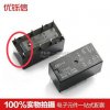
Here is the relay from the G7700 (Later Model). Not a LY or MY. Not an Omron, best I figure is its a Fujitsu...or no name brand!!
The Middle pair of terminals are the Coil, which eliminates a lot of modern replacements.
Maybe someone has the time to do some research, I drew blanks on my search.
View attachment 1248846 View attachment 1248847

Hello

Yes it it an old Fujitsu

upload_2018-8-2_16-52-29.jpeg

The DO24 indicates that it is a 24 V small signl relay.

The Omron G5V will work fine as a replacement.

You will have to wire the relay leads to the proper points on the PCB.

Here is my original illustration of how the rerouting should be done.
upload_2018-8-2_17-16-50.jpeg

Here are the coil points on your relay.
upload_2018-8-2_22-46-35.jpeg

Here are the coil points on the Omron G5V

upload_2018-8-2_22-50-56.jpeg

So it should be A LOT easier on your relay. You don’t have worry about routing/crossing that extra pair of leads.

In short ...just extend the legs of the Omron using wire, and slot it straight in.

Similar to this http://audiokarma.org/forums/index.php?threads/the-mighty-au-x1.672322/page-8
upload_2018-8-2_22-58-54.jpeg
 

Attachments

  • upload_2018-8-2_17-3-31.jpeg
    upload_2018-8-2_17-3-31.jpeg
    16.4 KB · Views: 28
Last edited:
Hello

Yes it it an old Fujitsu

View attachment 1249232

The DO24 indicates that it is a 24 V small signl relay.

The Omron G5V will work fine as a replacement.

You will have to wire the relay leads to the proper points on the PCB.

Here is my original illustration of how the rerouting should be done.
View attachment 1249235

Here are the coil points on your relay.
View attachment 1249306

Here are the coil points on the Omron G5V

View attachment 1249311

So it should be A LOT easier on your relay. You don’t have worry about routing/crossing that extra pair of leads.

In short ...just extend the legs of the Omron using wire, and slot it straight in.

Similar to this http://audiokarma.org/forums/index.php?threads/the-mighty-au-x1.672322/page-8
View attachment 1249318
Quite lightweight for a speaker relay though don't you think?
I was tempted to use the G5V, but was thinking it wasn't quite heavy duty enough for a speaker relay. So I went ahead and remote mounted a LY2 I think it was.

Good information though!!
 
Just updated the first post for AU-9900/9900A/11000.

Previously we had MY4-02-DC24 for the speaker relay (original Taiko RABK-2B). I've updated it to MY2-02-DC24.


Unlike in the AU-717 whose PCB not only has through-holes for (most) of the extra pins, the PCB also parallels the switches on the PCB. Each switch is rated at 3A, so you get a hefty 6A handling for a pair of paralleled switches.

Now, on the 9900A the PCB doesn't have any extra through-holes. If you just snip the 6 legs and do nothing else you are using only two, of 4 total, switches and dropping your effective current rating. The MY2 is 5A rated. MY4 is 6A, IF and only IF you parallel into two pairs, and is otherwise is only 3A if you only snip the 6 legs without doing anything else. So the drop-in replacement is the MY2. I'm looking at the MY4 right now, with the lid off, from the point of view of internal soldering and one half the job looks easy and the other half a bit fiddly.... so MY2 it is. Maybe one could parallel the MY4 switches externally, but those pins are short compared to the PCB thickness and it doesn't leave much space for decent current handling wire. Note that this stuff effects on lifetime of the contacts.

PS. Some nice pics in this old thread.
 
Last edited:
Regarding the AU-D9 relays - of which there are 3

This link to a post by @AUD101 explains it.
https://audiokarma.org/forums/index.php?threads/au-d9-for-restoration.878052/page-2#post-12939794

Briefly:-
RL2 (Speakers A) can be replaced with an MY4-02-DC24 (with the NC pins cut off).

see below for @AUD101's solution for RL3 (or Speakers B)
Parts acquired to replace the original Speaker B relay - Omron G2Z-222P-US

Relay: Omron G2RL-2 - 24V DC (note the two inner pins need to be cut off as they are redundant)

And a third relay RL1 (headphones) which can be replaced with a G5V-2 type miniature relay wired to the board with flexible (or solid) wire links.
 
Last edited:
Regarding the AU-D9 relays - of which there are 3

This link to a post by @AUD101 explains it.
https://audiokarma.org/forums/index.php?threads/au-d9-for-restoration.878052/page-2#post-12939794

Briefly:-
RL2 (Speakers A) can be replaced with an MY4-02-DC24 (with the NC pins cut off).

see below for @AUD101's solution for RL3 (or Speakers B)


And a third relay RL3 (headphones) which can be replaced with a G5V-2 type miniature relay wired to the board with flexible (or solid) wire links.

Good stuff. Will soon update summary of this into the first post of thread.
 
AU-D907X:
G4W-2212P-US-TV5-HP-DC24 X 2
G4W-1112P-US-TV8-HP-DC24 X 1

Thanks for that. added to front page.

Also, I just modified the AU-517 from MY2-02-DC24 to MY4-02-DC24. Although MY2 is a drop-in replacement the MY4 just need clipping 2 pins and the PCB automatically does the rest (see post #47; I checked the PCB for AU-517 does same trick as AU-717 with the extra pins of the MY4).
 
Just updated the first post for AU-9900/9900A/11000.

Previously we had MY4-02-DC24 for the speaker relay (original Taiko RABK-2B). I've updated it to MY2-02-DC24.


Unlike in the AU-717 whose PCB not only has through-holes for (most) of the extra pins, the PCB also parallels the switches on the PCB. Each switch is rated at 3A, so you get a hefty 6A handling for a pair of paralleled switches.

Now, on the 9900A the PCB doesn't have any extra through-holes. If you just snip the 6 legs and do nothing else you are using only two, of 4 total, switches and dropping your effective current rating. The MY2 is 5A rated. MY4 is 6A, IF and only IF you parallel into two pairs, and is otherwise is only 3A if you only snip the 6 legs without doing anything else. So the drop-in replacement is the MY2. I'm looking at the MY4 right now, with the lid off, from the point of view of internal soldering and one half the job looks easy and the other half a bit fiddly.... so MY2 it is. Maybe one could parallel the MY4 switches externally, but those pins are short compared to the PCB thickness and it doesn't leave much space for decent current handling wire. Note that this stuff effects on lifetime of the contacts.

PS. Some nice pics in this old thread.

My correction to the AU-9900A/AU-11000A above still stands, but I've now gone through an AU-9900 (non-A) and the PCB does indeed accomodate an MY4, with PCB which accepts all pins and parallels the 4 contacts into 2 pairs of 2 so you get the full 6A rating. According to the SM same should be true for non-A AU-11000.

So I will update front page splitting up the A and non-A versions.
 
Last edited:
My correction to the AU-9900A/AU-11000A above still stands, but I've now gone through an AU-9900 (non-A) and the PCB does indeed accomodate an MY4, with PCB which accepts all pins and parallels the 4 contacts into 2 pairs of 2 so you get the full 6A rating. According to the SM same should be true for non-A AU-11000. Also, the non-A version has only 2 relays, compared to 3 in the A version.

So I will update front page splitting up the A and non-A versions.

When the weather turns a bit I'll be going through my 11000A, will update anything I see that is different.
 
AU-717/517------->OMRON MY2-02-DC24
9090db/9090db-->OMRON MY3-02-DC24
8080/9090--------->OMRON MY4-02-DC24

those are the easy ones :p
9090db/9090db-->OMRON MY3-02-DC24
Did you mean 8080db/9090db? 8080db wasn't mentioned anywhere in this thread.
 
Just a note to check the first post in this thread for the correct information, some of the posts being quoted are less than accurate. ;)
 
Back
Top Bottom