• Please note that Audiokarma will be offline briefly for updates early on Monday morning, September 28th.

Sansui Turntable - Particularly XR-Q11

I also did not grease the rubber drive tires on the Q9. It seems that experience has taught me that only very specific greases can be used with buna/nitrile or EPDM rubber so that the rubber does not dissolve quickly. It also seemed that the miniscule level of torque transmitted by the mechanism would not be helped by a lubricant.
 
upload_2022-12-15_22-14-7.png
On the base, I installed the spindle+gear, double-gear, solenoid base, solenoid spring-and-plunger. I left the solenoid hold-down screws loose to tighten up after everything on the other side is all lined up. Note the ground lug goes under one leg of the solenoid bracket and the brass washer goes under the other side to keep this whole piece level.

I lubricated the gear teeth, worm gear, spindle inside, gear center brass piece (inside and out) and the solenoid plunger outer. Luckily, no rubber to worry about so far.
 
upload_2022-12-15_22-27-34.png
Next, installed and greased the red cylinder, the white plastic lifter and the micro-switches. I adjusted the micro-switches toward the red cylinder and tightened them down, then checked everything with an ohmmeter before moving on.

Then, added the damping washer (black thing in the center). It was pretty pliable so I did not bother to treat it. Again, I suspect it is not really critical to the whole function anyway. On top of the black damper goes a clear plastic "thrust plate." I cleaned this with isopropyl alcohol prior to installation.
 
I also did not grease the rubber drive tires on the Q9. It seems that experience has taught me that only very specific greases can be used with buna/nitrile or EPDM rubber so that the rubber does not dissolve quickly. It also seemed that the miniscule level of torque transmitted by the mechanism would not be helped by a lubricant.
Boy are you right! Worked automotive failure analysis and you don't know how many of those type compatibility issues cropped up, greases, oils, fuels, additive, silicones, car wash stuff attacking some of the latest-greatest polymer seals. I got to admit, I really missed having an IR here that I could throw a part on and 1 minute later, know what type of plastic or rubber it is. That's another reason I went to teflon grease, can't think of anything that teflon attacks, it's pretty much universally compatible.
 
So the rubber got hard. I'm a big fan of how and why to figure out how to fix this. And any professional rubber formulators out there, please forgive me in advance...

Rubber is an interesting and pretty old chemistry as polymers go. Today there's lots of types of rubber but the one we most likely have here is a butyl rubber. It all started with natural rubber which starts as a gooey sap from rubber trees. But it can also start from petroleum, synthetic rubber. The butyl name means 4 carbons molecules in a chain. Polymer means I react one 4-carbon butyl with another, then another and another till I have a long flexible chain of butyls. Well sometimes, the chains link up with each other in the middle. It's called a cross-link. Cross-links tangle things up and reduce the free length of a chain, so they reduce flexibility but increase strength.

Now gooey sap, even when dried, or the synthetic butyl pre-rubber is too flexible so it is intentionally vulcanized (aka crosslinked). This increases the strength and gives the rubber exactly the desired properties, depending on how much we cross-link.

Then folks take the pre-rubber and formulate it. They add carbon to make it black, fillers to make it cheaper, additives to make it vulcanize (zinc, sulfur, quinones), more additives (plasticizers) to add flexibility, more additives (antioxidants) to make the rubber last longer under sunlight and oxygen exposure. And lots of other stuff. Then they squish it out in an extruder to make sheets and parts.

So after 45 years, the plasticizers (polybutene and/or phthalate esters) have most likely degraded and/or evaporated. So we lose that flexibility. This is, more-or-less, a bulk change, all the way through the sheet or part.

And the antioxidants degrade. They were there to prevent reaction via sunlight and oxygen. Both sunlight and oxygen can attack the middle of the long, flexible chains and make the chains react with each other (cross-link). Extra cross-linking with time equals more hardness. But this is, more-or-less, a surface property that moves inward with time. And this is probably the feature we are fighting most here.

One other thing of note. Small solvent molecules can invade the chains of butyl rubber and swell the whole mess. Usually the cross-links hold everything together for some time but eventually, the rubber can dissolve in the solvent and the structural integrity completely disappears. The solvents usually evaporate pretty quickly so the swelling disappears and the rubber goes back to the original shape.

OK, that's a pretty good starting point for how rubber works and how it ages. But [next...] what to do, short of replacing the rubber with new rubber?
 
It may still be worthwhile to apply something to re-polymerize the compound. I would not soak the part, but apply a film and allow time for the reaction (could be days).

In the past I have used the original formula of Fedron, but it has since been withdrawn from the marketplace because two of the critical chemicals in the formula have been determined to potentially cause cancer in California residents only.

I don't have a problem with it.
 
The more I searched, the more I found that there are lots of posts about rubber rejuvenation, here on Audiokarma and elsewhere. These are some of the things I found mentioned online:

Rubber Renue by MG Chemicals
408A – oil of wintergreen (a salicylic acid) in xylene. Fun fact, aspirin is a salicylate.
408C - oil of wintergreen (a salicylic acid) in isopropanol
Fedron - all solvents? Can’t seem to find an active ingredient.
Maybe a trade secret and non-hazardous so it doesn’t show up on the SDS?
Varn – same as Fedron.
Gummi Pflege Stift – amine siloxanes,
Rubber Cleaner & Rejuvenator (Sprayway) – glycols and solvents
Maxpro Rubber Rejuvenator – all solvents xylene isopropanol, mineral spirits
Prisco rubber Rejuvenator – solvents and PGMA, a glycol
GC Electronics Belt and Drive Non-Slip – alcohol solvents and gum rosin
Rawn Re-grip - Limonene
Brake Fluid – glycols
TEAC TZ261 – unobtainium but it looks like it had solvents, a plasticizer and an antioxidant. Very good reports!
Caig RBR100L – solvents, chlorinated fatty esters, limonene

There is no lack of things folks have tried. Basically, you’re trying to swell the rubber with solvent, take off the top layer of dirt and maybe get a relatively non-volatile “plasticizer” back into the rubber. While this will not cure the extra crosslinking that happened due to UV exposure and oxidation, it might allow enough flexibility to help. But which one?

So why does plasticizer disappear in the first place? Most of the time, it evaporates, really slowly. As an aside, the original plasticizer in rubber usually degrades first, then evaporates, still kind of the same thing. The vapor pressure of a substance can give an indication of how fast it evaporates. For instance, atmospheric pressure is about 760mm. Water vapor pressure is about 24mm. Xylene is 106mm. Isopropanol is 33mm. PGMA 4mm, limonene 0.007mm, methyl salicylate (oil of wintergreen) 0.034mm, brake fluid is a mix, probably around 0.006mm.

Glycols, essential oils, anything that is non-hazardous, a thick viscous liquid with a low vapor pressure and soluble in a solvent that can penetrate but not destroy the rubber will probably work.

Also, things like xylene swell or even attack butyl rubber. Alcohols are much less aggressive.

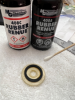
I ended up buying MG Chemicals Rubber Renue. They sell 408A and 408C without a lot of additional information about either. Both contain methyl salicylate (oil of wintergreen) as the longer-term plasticizer that soaks in. 408A is more aggressive with the solvent being xylene. 408C could be considered more of a surface cleaner that also infiltrates some plasticizer into the rubber.
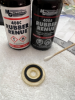
upload_2022-12-16_19-48-21.png
In my experience, 408C was not particularly effective. 408A was much better but make sure you use it with good ventilation. In the end, neither improved the clutch engagement enough for good reliability. I think it would be interesting next time to try the Rawn Re-grip or the CAIG product with limonene, you know, the stuff from lemons with a pretty low vapor pressure. Maybe even just mix some lemon oil with xylene. Or maybe the Gummi Pflege Stift with silanes that are typically used to surface treat your hair. Or maybe even the brake fluid, probably DOT3 which has no borate esters. The borate esters in the DOT4 would not be helpful here, probably quite the opposite. I will definitely not be using the product with gum rosin. Gum rosin is really just pine tar in solvent. Something like that in this complex mechanism. Not!

But really, they will all eventually just evaporate away. So, whatever has the lowest vapor pressure will probably be the long-term winner, as long as the accompanying solvent can carry it in and then evaporate relatively quickly without destroying the rubber in the process.

With the Rubber Renue, the hardened surface remained. After several treatments over a period of a couple of days and reassembly, the solenoid would engage and the tonearm would move but the engagement was not 100% for the tonearm lifter mechanism when the solenoid was disengaged.

I finally ended up treating the surfaces with 408C, letting it soak in for a couple of minutes and then touching up the surfaces with a micro-file:
upload_2022-12-16_19-48-38.png

I think the lesson is this, swell and clean the surface, then take off as little as possible of the hard, oxidized top layer.

I reassembled the rest, thrust washer, top plastic piece, new rubber damper clasp washer, then treated, files and cleaned the rubber that engages the copper disc.
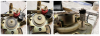
upload_2022-12-16_19-49-8.png

Finally treated, filed and cleaned the rubber on the tonearm side of the mechanism:
upload_2022-12-16_19-49-23.png
 

Attachments

  • upload_2022-12-16_19-47-58.png
    upload_2022-12-16_19-47-58.png
    90.4 KB · Views: 3
  • upload_2022-12-16_19-47-58.png
    upload_2022-12-16_19-47-58.png
    90.4 KB · Views: 2
Last edited:
It may still be worthwhile to apply something to re-polymerize the compound. I would not soak the part, but apply a film and allow time for the reaction (could be days).

In the past I have used the original formula of Fedron, but it has since been withdrawn from the marketplace because two of the critical chemicals in the formula have been determined to potentially cause cancer in California residents only.

I don't have a problem with it.
Just in time, @Watthour just finished with the above.

The mechanism WORKS! I get up and down, I get back and forth!

And at least if nobody else uses this long story, I can use it if I ever fix another one of these...

There are still some issues with sensing where to start, returning at the end and and the exact positions to stop (tonearm get almost but not all the way back when I hit return). But everything functions! I am ecstatic to be to this point.

I'll probably be tapping you for help as I figure out how to fine-tune the operation.
 
It sounds like you will be getting into the tone arm positioning optical array soon. Adjustment there is sensitive, but can be done. As for the track/selection sensor on the Q11, I have no advice.
 
It sounds like you will be getting into the tone arm positioning optical array soon. Adjustment there is sensitive, but can be done. As for the track/selection sensor on the Q11, I have no advice.
We'll start with optimism, here's what is working:
- press start, tonearm up and swings to record
- press stop, tonearm returns almost all the way to home
- tonearm up-down works
- repeat seems to try to repeat
The less optimistic:
- finding the beginning of the record is intermittent
- track select doesn't work at all
- end of record not automatically returning
- return is not quite all the way onto the rest
- mechanical - the anti-skate weight is not engaged until midway through the record.

From what I can tell initially, I believe the XR-Q11 uses the sensors to find the record start, since it does not have a record size select. It does have the internal mask in the tonearm mechanism but unlike the other models, I'm not sure it uses this:
upload_2022-12-17_19-33-56.png
Time to read up on the operation...most of it seems like it relates to the sensors.
 
With a quick perusal of the SM, it looks like first I need to check the signal of sensor B to the MPU (uPD546 IC pin34). My suspicion is that the LED has failed, similar to that "Turntable from Hell" video, if I recall correctly.

Next, the whole cartridge sensor E & F workings...probably a similar LED failure.

Any ideas how to adjust the anti-skate? The little thread that attaches the levered weight to the tonearm is limp until the tonearm gets well into the first 10 to 20% of the record. I'm sure it's in one of the manuals, just haven't located it yet.
 
Haven't had time to check the actual LED's yet but found the following datasheets for the A and B sensor emitters (SR106CA an NEC part) and the E sensor emitter (LD261 an Osram part). Unbelievable but a seller in Bulgaria has the first one, seller in Florida has the other. They are so inexpensive, I got 10 of each for under $12 total w shipping. It could be 2-7 weeks to get them...

Now to find out if I really need them...
 

Attachments

Finding the start of the record and dropping the needle... it turns out that it is more involved than the QR-X9 or other Sansui turntables. The engineer decided that since they had a sensor on the end of the tonearm to sense and select tracks (sensor E) AND a sensor at base with a plate with two holes that is set for either a 17 or 30cm (sensor A) AND a computer that can make complex decisions...
upload_2022-12-18_18-34-35.png

And just to make it a little bit more challenging, sensor E has it's own circuitry before the computer that splits the signal into two signals, E2 which creates a pulse upon seeing each track so the computer can keep a count of the number (and probably position) of each track, and E3 which senses and locks high for the duration of the time during the lead-in or gap.

So the upshot, depending on the operation, the vinyl beginning requires sensing by
- sensor E and A,
- sensor A and E, or if in whole music play or if song 1 is selected,
- sensor E or A.
And thus my intermittent operation, probably one sensor is working, one is not. So in some modes, it will drop the needle, in other modes, it thinks there is no record present.

Time to go make some measurements...
 
Here’s a clip of the circuit we’re looking at:
upload_2022-12-21_10-43-41.png

Sensors A and B are the box on the left with the associated circuit board S-0061 on the right. The connector to the main boards is the little box with the four arrows. I label them 1 to 4, top to bottom. The sensors consist of two parts, the LED emitters (LD1 and LD2) and the phototransistor detectors (Q1 and Q2). The detectors are an NEC part, PH101. Attached are the datasheets for the emitters and detectors...

So how should this work? It looks like the LED’s are constantly lit by a supply voltage across two of them in series with a current limiting resistor of 470ohms. As an aside, “constantly lit” for an old piece of equipment looks like a real clue. The data sheet says the voltage drop across each should be 1.6V each or 3.2V total for the two of them. That leaves 6.8V across the 470ohm resistor and (using Ohm’s Law) 14mA through each LED and the resistor, since they are all in series. 14mA is well within spec for the LEDs and suggests we should be getting somewhere around 60% of the typical intensity of light from the devices. A little further searching on the internet indicates a common failure mode for these gallium-arsenide-phosphide semiconductors is a gradual reduction in the ability to emit light…they become dim and emit heat instead. There’s probably no real measurable voltage change other than emitting less light and more heat. It is possible for these LEDs to fail catastrophically but that’s less common. It can go open or short. We might see that with a voltmeter by looking at the expected voltage across each LED and the resistor.

How about the detectors? They are transistors. In general, I kind of look at a transistor as a variable resistor from the top to bottom wire lead (the emitter to the collector). The resistance is controlled by how much I put on the left wire lead (the base). EE’s please don’t flame me! It’s a simplification.

How much of what that I put on the base? Well, if it’s a circuit with a wire lead, it boils down to how much current I put into the base. If it’s a phototransistor, it’s how much light I put on the base. A phototransistor has a little lens instead of a wire lead. The base itself is made of a material that is sensitive to light and produces electrons, a current. If you look at the datasheet, that not really how they term it, though. It’s more like this:
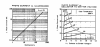
upload_2022-12-21_10-45-0.png
The chart on the left shows the amount of current produced by the base depending on the amount of light the base sees. Let’s say it’s dark and the base produces maybe 1mA of photo current. And let’s say when it’s lit, it produces 30 or 40mA of current. Go to the chart on the right and we see the dark 1 mA photo current will give us a big voltage drop collector to emitter, close to 15V. In other words, the transistor is acting like it’s got a really high resistance. One note, the graph was produced using a source voltage of 15V. We have only a 10V supply. So we will not drop 15V but more like 10V across the phototransistor when it is dark.

On the other hand, shine a light (or our LED emitter) on the base and the 30 or 40mA of current that the base produces results in a voltage drop of about 2V or less across the emitter-to-collector. The datasheet suggest saturation (lower limit for the voltage drop) at about 1.5V. In other words, a much lower resistance. So the voltage drop across the transistor should be between 1.5 and 10V depnding on how much light the base is seeing.

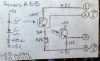
The circuit board has some strategically placed test points as well as the more easily accessible connector. I re-drew it so it is easier to see:
upload_2022-12-21_10-45-39.png
The test points (TP3 to TP1) were conveniently located to measure the voltage across the resistors in the circuit for sensor B rather than the transistors. The resistors just get the voltage from the source (+5V to -5V = 10V) minus the voltage drop from the transistor (1.5V if the transistor is lit, ~10V if the transistor is dark). So, we should expect to see TP3 to TP1 at 0 to 8.5V. Service manual suggests anywhere from 0 to 4.5V to 0 to 8.0V, so that fits. And the engineer designed it to be OK if the LED dropped in brightness by almost half! And even threw in an adjustment resistor in order to account for maybe even more variation. And even included a procedure to adjust the distance between the mask and the emitter to help even a little further. In general, IMHO a well thought out design for both manufacturing variance and later servicing!

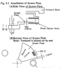
OK, so now I know, where to test (voltages at TP3 to TP1, maybe across some of the leads at the connector and maybe across the LEDs). And I should rotate the tonearm to the positions where the mask (screen plate) either let’s light through or blocks it:
upload_2022-12-21_10-48-24.png
 
OK, I finally did some actual work. Here's the places I wanted to use to get some voltages:
upload_2022-12-22_21-25-54.png
These are the test points of interest.
- voltage drop across the LEDs = 3.2V [good]
- gnd to + supply = +5.00V [good]
- gnd to – supply = –5.00V [good]

Also visually confirmed that both red LEDs were illuminated. So far, so good.

Sensor A and Sensor B output voltages are measured between either the orange or yellow wire and -5V supply (TP3). If the LEDs fully illuminate the phototransistors, the phototransistors are “on” and have low resistance. When they have low resistance, we should read nearly the 10V (+5V compared to -5V). When the screen plate blocks the LEDs, the phototransistors are “off” and have a high resistance. When they have a high resistance, we should read very near to 0V.

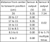
The Sensor A and Sensor B output will also depend on the position of the tonearm. Initially, the screen plate does not block either sensor. A short way off the tonearm rest, the screen plate blocks both sensors. For Sensor A., the screen plate has two gaps, one at what would be the leading edge of a 30cm diameter record and a second one at what would be the leading edge of a 17cm diameter record. For Sensor B has a bunch of small gaps in the area where the end of the record would be expected.
upload_2022-12-22_21-27-13.png

So really, this all looks OK, too. Sensor B is a little low but according to the service manual, it should be adjusted to between 4.5 and 8V. Just to be sure, I'll drag out the oscilloscope and check it like they suggest...
upload_2022-12-22_21-31-11.png

So my initial conclusion, for the lead-in, Sensor A is probably not the problem, it's most likely Sensor E. And the end-of-record return, well, I have no needle yet and the end-of-record timing cycle may be critical for it to work correctly. I'll need to get that squared away before I pass judgement. It looks like it is not as simple as the tonearm passing a certain point in the record but rather, requires a certain series of on-off signals to initiate the return.

To be sure, I probably also need to check the sensor signals at the computer input but I expect that the couple of transistors and op amps that get the signal from the sensors to the computer are probably not the problem.
 
Your tenacity is admirable. It would be nice if there were an actual text of the operation sequence at the TTL logic level, but I suspect it does not exist. Or at least, not yet.
 
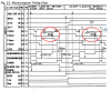
THX, Watthour! Brilliant...I had not looked closely at the XR-Q9 manual previously. There are a bunch of those timing charts but the one in the XR-Q9 for the B-Sensor is interesting. Although the input to the computer is quite different, the sensor and screen plate are the same. And here is the timing chart:
upload_2022-12-23_7-39-11.png
It looks like at the end-of-record it wants to see consecutive signals from Sensor B that are less than 1.3sec if it is a 30cm diameter record and less than 1.0sec for a 17cm diameter record.
 
Back
Top Bottom