• Please note that Audiokarma will be offline briefly for updates early on Monday morning, September 28th.

Sansui Turntable - Particularly XR-Q11

@mootej, Excellent work. I just have to say you have now provided documentation of the definitive repair and adjustment of these tables. I never thought when I made my first post concerning the XR-Q models here (nearly 20 years ago!) that someone would ever do such an in-depth tear down and tutorial on these.

With what you've posted here (building upon the work previously done by @Watthour) is a remarkably detailed run down on nearly every angle of the operation and restoration of these units. Consider me duly impressed with your dedication and resolve to get it done.
 
@mootej, Excellent work. I just have to say you have now provided documentation of the definitive repair and adjustment of these tables. I never thought when I made my first post concerning the XR-Q models here (nearly 20 years ago!) that someone would ever do such an in-depth tear down and tutorial on these.

With what you've posted here (building upon the work previously done by @Watthour) is a remarkably detailed run down on nearly every angle of the operation and restoration of these units. Consider me duly impressed with your dedication and resolve to get it done.
Well @Sansuiman that's what retirement and a long winter will do to you! My daughter was over at Christmas and said, "Looks, dad's blogging, and he's got at least two or three folks following!"

But oh it gets better. Wait till you read about the groove-less records and the trip to the record store. I saved $25 and spent $100 on all the albums I couldn't pass up.
 
upload_2022-12-27_20-27-46.png
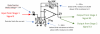
Here’s the circuit. I measured the voltages from ground to the wires coming from the tonearm headshell (where circuit board S-0060 with the LED and Sensors E and F is installed on the end of the tonearm) to circuit board S-0056 (plugged into the main circuit board, shown below).
upload_2022-12-27_20-28-31.png
The LED appears to be soaking up 1.2V and since the 17.1V is across a 630 ohm resistor to ground, the current is (V/R = i) 0.027A. Based on that, take a look at the curve below from the LED datasheet. We’re operating perfectly (red dot) and everything seems to be in order.
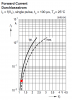
upload_2022-12-27_20-29-14.png
Next up, testing the output of the phototransistors. Same thing as Sensors A & B, the phototransistor will drop a major portion of the 18 volts when dark and near 0 volts when lit. Conversely, the resistor in series with the collector that goes to ground will drop near 0 volts when the phototransistor is dark and near 18 volts when the transistor is lit. Since we are measuring the voltage drop across the resistor, it’s the second one we should expect.

But wait, we’re bouncing the LED off a record and reflecting it back. We shouldn’t expect that we’re going to get a whole lot of light back. So let’s expect that we will get not much signal (near 0V) across the resistor when the LED is bouncing back off of a groove on the record and some nominal voltage (near???) when the LED is bouncing off a reflective gap in the grooves.

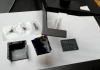
It would also really help to have a groove-less record to use for testing so we can get the most signal back while we test and adjust things. OK, Amazon sells a groove-less record for like $25! Ouch. And there is a wait time! Ouch. A quick internet query and trip over to Dearborn Records used section turned up the following:

I got:

Joe Jackson – Big World --> 3 sides of music on two LP’s, one side of which is blank.
Joan Armatrading – How Cruel --> minimal songs on one side with really big gaps.

Here are a few other possibilities (not verified):

Johnny Winter – Second Winter
Utopia – Utopia
Smashing Pumpkins – Adore
Jimi Hendrix – Radio One
Neil Young – Americana
Rarebird – Epic Forest

Yes, I am still to this day amazed at the internet and the obscure knowledge you can find without even really trying!

 
I placed the groove-less test record on the platter and moved the tonearm from the rest to the record. Voltage on yellow (Sensor F output) reads low (<50mV) when the tonearm is lifted (dark, no reflection), about 250mV on the arm rest (probably reflecting off the somewhat shiny finish on the base) and 500 to 700mV over the shiny test record surface.

Voltage on purple (Sensor E output) reads low (<10mV) under all conditions. This is very suspicious!

Adjustment of the side screw does not affect either sensor reading. I was hoping, maybe, Sensor E was just out of alignment. No luck.
 
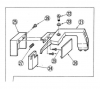
Time to disassemble the sensor head. Here’s the relevant info from the service manual. By the way, if anybody’s got a lead on 70122500, an uncracked dustcover, let me know. I will be trying to work miracles later with my cracked dustcover and something called Mesquite Man’s Cactus Juice. I do not have high expectations. @Sansuiman I still hope to strike up a deal for a Q9 for parts now that the Christmas package rush is over!

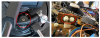
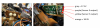
Here's the sensor assembly out at the end of the tonearm:
upload_2022-12-28_8-31-32.png
First, take out two little screws (M1.4x2) that hold the sensor head onto the tonearm (part no. 20). M1.4, jeez, how small do they make these screws? Next, remove the sensor bottom plate (part no. 17) using a super small spade screwdriver to gently pry the cover off. Gently bend the sensor assembly (part no. 15 & 16) forward but be careful with the really, really tiny wires! Don’t pull, the wires have no slack.
upload_2022-12-28_8-33-4.png
Very curious, what’s the white stuff? It comes off. Theories? Maybe a component blew up and shed it’s guts? Something corroded? Some part or piece out-gassed? Did they use CA glue and it outgassed? Not sure but very suspicious.
 
Next remove the M2x8 adjusting screw (part no. 19) all the way. The spring (part no. 18) underneath it needs to come out, too. Watch out, mine sprung out and it took about fifteen minutes to [luckily…] locate it.
upload_2022-12-28_8-34-46.png
Next remove the sensor cover (part no. 16) again with gentle prying and a tiny spade screwdriver. This is what it should look like:
upload_2022-12-28_8-35-29.png
You’re left with a bunch of tiny parts that are really easy to lose, a couple of covers and sensor assembly S-0062 (part no. 15) hanging down by really tiny fragile wires from the sensor holder (part no. 14).

From a 2013 post...
https://audiokarma.org/forums/index...table-with-a-big-problem.498757/#post-6476992
...that had an XR-Q11 with the sensor head torn off from a post a long time ago, I’m pretty sure a lot of this could be duplicated with a 3D printer and maybe some ingenuity. I also think a Sansui FR-D55 could be a donor for parts. Here’s from the D55 SM:
upload_2022-12-28_8-38-23.png
Looks pretty similar.
 
OK, but back to this beast. Look what I found:
upload_2022-12-28_8-39-49.png
Now, you might conjecture that I did this during disassembly. The interesting part is that all three of the other wires are solidly attached and this happens to be the purple wire, the sensor wire with a suspicious lack of signal! Let’s see if that will fix things…
 
Well, I need to backtrack a little. Prior to disassembly of the sensor assembly, the low signal was actually the yellow wire (Sensor F), not the purple (Sensor E). This makes some sense since the tonearm can find the record start but can only do this when it sees a signal from both the A and E sensors. So a bad Sensor E did not make sense.

It also suggests I broke the purple wire on disassembly. It's all resoldered now, what a bear to strip and solder 34 AWG wire with no room for error!

OK things back to where they were, signal good on Sensor E, bad on Sensor F, not much time wasted on that blind rabbit-hole. I did find a better way to test these phototransistors. I removed the sensor head so I could tilt it and I shine my TV remote into the head. I can get a superb, 6V out of Sensor E this way. Sensor F now responds, but only with 60mV max. I guess I need to disassemble again, check the wiring connections from main board to the sensors with an ohmmeter, then start suspecting the phototransistor(s).
 
I don't know if this is good or bad. I checked the output from the phototransistor on the sensor board with the TV remote: +5V at least, so the phototransistor is good. I check the continuity of the yellow wire from the main board to the end of the tonearm: open circuit. Arrgggh. Needing to replace that wire will be, shall we say, tedious.
 
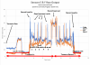
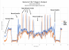
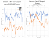
Good news, I hit a couple of the connections with the soldering iron, reassembled a few times and now both sensors are working! I put on a 5-track record and ran the tonearm across and back by selecting Track 7. I monitored the two sensors with the oscilloscope, E the lead sensor and F the trailing sensor. Sure enough, it's working:
upload_2023-1-3_16-58-16.png
I can see where the tracks are, now I need to go through all of the service manual calibration routines so the computer sees them too.
 
Last edited:
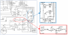
The sensors are working but the microprocessor (MPU) does not seem to be seeing the signal correctly. The block diagram is the easier to read (hahaha!) compared to the more detailed schematic. It shows a whole lot of stuff in between the sensors and the MPU:
upload_2022-12-31_8-29-25.png
 
The block diagram shows a string of op-amps that split the signal into three different parts, eventually feeding into some IC’s labelled TC4528BP. According to the block diagram, the op-amps are performing three functions. First is a DC amp that most likely takes the sensor signal and amplifies it. Next is a B.P.F. which I’m guessing is a Band Pass Filter, probably filtering out low and high frequency noise. Lastly is a comparator, probably to trigger up when the signal is above a certain level and trigger low when the signal is below a certain level.

Here’s Stage 1 for both the E and F sensors. This is supposed to be a DC amplifier but it looks like they had a little filtering in mind, too.
upload_2022-12-31_8-31-23.png
And the datasheet for the op-amps attached, though I hardly looked at them, op-amps are pretty generic...
 

Attachments

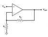
I’m having to remind myself all about op-amp circuits. Below is a typical diagram for a non-inverting input op-amp amplifier. The input come into the non-inverting input (“+”). Feedback comes from the output through R2 and returns back into the inverting input (“-“). It’s an amplifier with Vout= Vin x (1 + R2/R1) or a voltage gain of Gain = Vout/Vin = 1+ (R2/R1).
upload_2022-12-31_8-36-8.png
For Stage 1, if we ignore the capacitor, we get Vout/Vin = 1+(680K/100K) or Gain = 7.8. The capacitor acts like it’s not there (an open circuit, it blocks DC voltages) at low frequencies and like a wire (dead short, high pass) at high frequencies. So, at low frequencies, the gain is indeed 7.8. But at high frequencies, the capacitor acts like a zero-ohm resistor, a wire, and Gain= 1+(0/100K) = 1, a voltage gain of 1, aka a voltage follower (output = input). The cutoff frequency, the frequency that the circuit starts reducing gain from 7.8 to 1 is calculated by f = 1/(2πRC) = 1/(2 x 3.14 x 680K x 220pF) = 1064Hz. Well, at least I hope I have that right…

Summarizing, this is a low pass filter circuit that amplifies approximately 8x but helps to cut off any high frequency noise above 1KHz by not amplifying it.
 
Last edited:
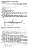
The prelude to this, section 3-10 of the service manual: get test disks and a ruler and a good voltmeter (done), set the tonearm height to 7mm+/-0.5mm (done – it uses a little screw on top of the up-down lifter),
upload_2023-1-1_15-51-12.png
then adjust the Sensor E & F sensitivity so that the output of the Stage 1 op-amps is 5 volts (lifter up, tonearm 10cm from center, on a test record with no grooves – done).
upload_2023-1-1_15-52-16.png
 
I originally measured the voltage for Sensor E, output at op-amp at 4.65V (TP5 to ground) and turned VR1 up until I got 5.0V. For sensor F, the output out of the op-amp (TP6 to ground) was 4.19V and I turned VR2 up until I got 5.0V. I did not run a new plot for the sensor raw output. The key to that is, the previous plot of the sensor raw output is a little low since I turned them up some 7% and 20% respectively. When we look at the op-amp Stage 1 output, it will be a little higher than expected because of this...

Well, here it is:
upload_2023-1-3_21-11-57.png

Raw signal = 0.1 to 0.3V at groove, 0.4 to 0.6V at gap.
Op Amp Stage 1 = 1 to 3V at groove, 4 to 5V at gap.

In other words a voltage gain from Stage 1 of 7x to 9x after we account for the fact that I turned the raw output up 10 to 20% and did not re-run the raw sensor output plot.

Right on Target!

How about the noise filtering? Here’s a close-up of before and after. I tried to adjust the vertical scale to account for the approx. 8x amplification and kept the time scale constant.
upload_2023-1-3_21-14-44.png


Qualitatively, looks like high frequency noise is down. OK, Stage 1 is good, signal amplification is ~8x, noise >1KHz amplification ~1x. Check! On to Stage 2…
 
Last edited:
Sensor E

For the 2nd stage, noted as B.P.F. (probably band pass filter), the Sensor E signal comes from Stage 1 and goes into this Stage 2 op-amp. Stage 2 has two outputs which we’ll label E2 and E3:
upload_2023-1-1_16-1-18.png

This is an interesting circuit. First off, the diode blocks anything below ~1.3V.

The feedback circuit will have a resistance of 910K-ohm below 37Hz. Above 37Hz, the capacitor starts acting like a wire instead of an open circuit and the feedback resistance eventually goes to zero at high frequencies. The ground-to-inverting-input circuit will have a resistance of 100K at high frequencies since the capacitor will act like a wire. At low frequencies, the capacitor will act like an open circuit and the resistance will go to infinity. Remember the gain formula? Gain = 1+(R2/R1). We have three cases:

1. Above 37Hz, gain = 1+(0/100K)= 1
2. Between 16Hz and 37Hz, gain = 1+(910K/100K) = 10.1
3. Below 16Hz, gain = 1+(910K/infinity) = 1

In summary, anything under 1.3V is blocked, anything below 16Hz or above 37Hz, gain of 1 (voltage follower) and anything between 16 to 37Hz, a gain of 10.1, a bandpass filter! Note that if we have a gain of 10.1 and an input signal of 1.3 to 5V, the output will be 13 to 50V. The supply voltage to this chip is only 18V so basically, this output should max out with virtually anything that gets through the diode and the bandpass.

Just off the top, this looks like a problem since the voltage between gaps, heck, really everything seems to exceed the 1.3V cutoff. Well, maybe the bandpass filter will take care of it. But it looks like the phototransistor “dark” voltage is kind of high. We’ll need to measure.
 
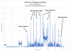
Well, here it is, Sensor E Stage 2, using the same record and having the tonearm scan across and back…
upload_2023-1-3_17-12-35.png

Yeah, well maybe, but it sure would be a lot cleaner if the "groove" voltage were below the diode cutoff voltage. For now, I'll file that one under "interesting" and we'll move on to look at Stage 2 for the F signal.
 
Last edited:
Back
Top Bottom