• Please note that Audiokarma will be offline briefly for updates early on Monday morning, September 28th.

Sansui Turntable - Particularly XR-Q11

The XR-Q11 manual was not nearly as descriptive about how it figures out the end-of-record. The manuals do an ok job with the timing diagrams and the verbiage.

As I had mentioned in another thread,
https://audiokarma.org/forums/index.php?threads/sansui-computer-turntables.1011580/
I would love to be able to dump the program. But so far, the guys dumping the 70's and 80's handheld arcade game roms haven't really posted much about the technique and right now, the energy barrier is a little high. Looks like it requires wiring up and programming a PIC, then figuring out exactly how the test mode on the chip works to get a ROM dump. A guy that goes by Kevtris would probably help but I have not yet tried to contact him. And reading assembly language is no picnic either.

But just imagine, if you had the code, you could maybe pull the chip and replace it. Emulate or even extend the code. Add bluetooth...maybe next year...

Well, better get it working as-is first!
 
@Watthour I must admit though, I am a little baffled by the Q9 circuit complexity compared to the Q11:
upload_2022-12-23_8-29-13.png

Is this just a couple of buffers on Sensor A and a timer circuit and a gate that either lets Sensor B through to the computer or not, depending on the timing?
 
Here's the Q11 circuit, I don't think I see a timer here? Are those diodes around the transistor just clamps?
upload_2022-12-23_8-46-49.png
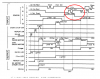
And the timing chart:
upload_2022-12-23_8-55-53.png
 
I have the experience of reading the bin files from early GM ECM PROMs, and a writer. The difficulty was in decoding the mask files for the binaries to make sense of it all. To complicate matters, those changed from year to year. I still do a little occasional PROM burning and UV erasing, but it's pretty rare these days.
 
@Watthour, I've done PROM dumping and programming on GM ecms and BCMS (late 80's/early 90's 3800 engine vehicles primarily) and on pinball/arcade uprights. These NEC 4 bit CPUS are more like a mask ROM, difficult but not impossible to dump the image. Definitely not as straightforward to do as a common OTP, UV or EEPROM though. I have to convey my respect for the guys who figure out hacks to do that stuff.
 
@Watthour, I've done PROM dumping and programming on GM ecms and BCMS (late 80's/early 90's 3800 engine vehicles primarily) and on pinball/arcade uprights. These NEC 4 bit CPUS are more like a mask ROM, difficult but not impossible to dump the image. Definitely not as straightforward to do as a common OTP, UV or EEPROM though. I have to convey my respect for the guys who figure out hacks to do that stuff.

GM? I was a GM guy, until a year ago last July. Failure analysis, tearing apart lithium ion batteries...

@Watthour does that explain the tenacity? :whip:

Those arcade guys were actually pulling the top of the chips, etching them, then reading the mask ROM with a microscope! One guy figured out the test code that allows a non-destructive ROM dump using an undocumented test mode. Talk about tenacity!
 
That's bordering on pathological...

BTW, I still am one of those guys. I just ordered a vehicle from Lansing on Wednesday. Maybe it will arrive by 2025, but no one is holding their breath.
 
Last edited:
Most of my PROM work on cars was related to tweaks in the 1988-91 Buick Reatta, of which I own four presently. Yes, I have another obsession aside from Sansui. The 88 and 89 models had a 6" CRT touchscreen for radio, additional gauges, diagnostics, climate control and other functions. All driven off an 8088/8052 based embedded system with a mono VGA output.

I tweaked some screen displays and messages by editing image bitmaps and text in the ROM. Was a slick idea too far ahead of its time, so was scuttled in favor of more traditional radio and climate control panels in the 90-91 models.

IMAG0170.jpg
 
@Sansuiman way too cool, you guys!

Back to the Q11, I've got to rave on a little usb scope I picked up cheap on ebay for like $50. It is a PCSU200, 2-channel scope and signal generator. It's great for audio work. I avoided pulling out the 50lb Tektronix or the portable 20lb Tektronix that really could not have done this anyway since they are not storage scopes. And several thousand dollars for a real nice current digital scope, well, no way.

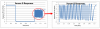
I did the suggested test, hook the scope up to TP1 (+) to TP3 (-), monitor the voltage and run the tonearm from the tonearm rest to the record finish. This is what I got:
upload_2022-12-23_20-28-51.png

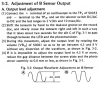
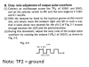
So, here again was the procedure:
upload_2022-12-23_20-34-49.png

OK, where am I at? I'm a little confused that the dark voltage is kind of high, 2V when it should be zero. The difference is definitely out of spec. I guess I'll try adjusting higher. The manual isn't real clear other than the difference needs to be 4.5 to 8V. What do you think?

Also need to check the duty cycle...

And also, please guys, take a look at the input circuit from the sensors to the MPU and tell me what you think they do. I mean, the ultimate goal is to get a 1 or a 0 to the MPU for "sees the gap" or "does not see the gap." What sensor voltage will be "0" and what voltage will be "1"?
 
Last edited:
OK, never mind, went ahead and adjusted VR2 and now the auto-return works fine.
upload_2022-12-23_21-28-47.png
Now within spec, I guess the low voltage end does not need to be zero.

Next...the E and F sensors and the track selection...

But until then, Merry Christmas, everybody!
 
OK still waiting for Santa Claus. Until I hear the reindeer...

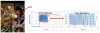
Per usual, the knowledge comes in little snippets. I followed the 2nd procedure for Sensor B:
upload_2022-12-24_13-7-21.png
upload_2022-12-24_13-7-50.png
upload_2022-12-24_13-9-21.png
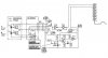
Here’s the knowledge snippet…I’m trying to figure out above, why is the dark voltage so high and how will it know if the sensor is on or off? So, the engineer at Sansui realizes that the slits on the screen plate are really small and Sensor B never really turns all the way on or all the way off, unlike Sensor A. Here is the circuit:
upload_2022-12-24_13-9-52.png
So VR2, which we adjusted first, is a total amplification control. It makes sure we have enough signal from Sensor B so that we see enough difference between “lit” and “not lit”, thus the spec for between 4.5 and 8V difference.

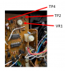
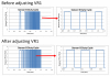
The transistor circuit, though, I still don’t know exactly how it works, but it is a double clamp circuit. It will clamp low when the input voltage is below some level and clamp high when the input voltage is above some level, basically acting like a switch to tell the computer whether the analog signal from Sensor B is “on” or “off”. The transition voltage is set by VR1. By looking at the “duty cycle” of the output to the MPU (TP4 versus ground), it tells us how much of the analog signal from Sensor B is above the transition point and how much is below. To center it, each half of the square wave low versus high should be about equal in length (assuming, of course, we move the tonearm at a fairly constant speed).

In practice, the control is really touchy. It seems to work fine if we get it close. You can see “before” was not that far off. I moved the potentiometer, wow, almost not at all. The “after” is now on the other side of OK. But it works.

Well, that’s about as exhaustive as it needs to get for Sensor A & B, which are probably, more-or-less the same for at least a couple of the Sansui turntables.

Oh, one other interesting side note, diode D3 is a VD1212. Search Audiokarma for that one! Apparently, it is a varistor diode, known to many by the moniker, "Shoot on sight." In other words, "Replace!" I guess the failure rate is quite high, at least in the opinion of some. If I eventually decide to re-cap the electrolytics, which are almost always, at this age, maybe working but sideways to spec, I'll snip those diodes, too. They can be replaced with two 1N4148 in series. Basically, they are just providing a reference voltage. It's good I dug into that circuit. I would have never found that hint otherwise.
 
Last edited:
Here is the really obscure datasheet for the VD1212 (per @clinic-audio Big Thx!). He had interesting comments here:
https://audiokarma.org/forums/index.php?threads/can-i-use-2x1n4149-to-replace-a-vd1212.886219/
and some nice iV charts that would suggest if you do replace this varistor diode, the reference voltage will probably change some and you may need to tweak VR2 again. But I think this is not a critical replacement anyway, kind of a brute force analog to digital conversion that should be fairly immune to issues, either not replaced or replaced with the two 1N4148 diodes in series.
 

Attachments

  • VD1212-datasheet.JPG
    VD1212-datasheet.JPG
    72.5 KB · Views: 4
Arrgggh. I'm updating the post keyword tags because I notice that a bunch of the Sansui turntables use the A and B sensors and I figure it may be helpful to someone in dire need of a fix. I come across the Sansui FR-D55 and I notice it has the sensors. Then I notice it also has the track selection. I'm intrigued since I think this is such a cool feature and I really didn't realize there were [any...] very many turntables like this other than my youth-coveted Accutrac. So of course I head over to Ebay on Christmas day just to see...

Of course, there is one, auction to be complete in about 9 hours, no bids and minimum bid at $20, $30 shipping! Who can pass that up? Of course I have to throw in a hail mary $20 bid, sure that someone will dive in at the last second. Well, no, I wake up to find out I am now the proud owner of another orphan from the land of misfit toys.

upload_2022-12-26_14-47-23.png
 
Nice. It had ecaped my attention that the FR-D55 also had track selection. Will be interested to get your assessment of it's build quality versus the XR-Q line, as the latter were the top model line of the era (followed by the lone ranger, XP-99).

Also curious if the FR-D55 will need the same general service to be usable. I don't imagine Sansui did any serious redesign of the auto mech/sensor system as found on the Q11, as that was a sunk cost for work already done.
 
Nice. It had ecaped my attention that the FR-D55 also had track selection. Will be interested to get your assessment of it's build quality versus the XR-Q line, as the latter were the top model line of the era (followed by the lone ranger, XP-99).

Also curious if the FR-D55 will need the same general service to be usable. I don't imagine Sansui did any serious redesign of the auto mech/sensor system as found on the Q11, as that was a sunk cost for work already done.
I'm going to need a storage spot like yours soon if I keep getting more turntables! Yes it will be interesting to see this beast. All the internals looks the same or very similar to the XR-Q11 with a few exceptions. Outside is not as nice and it weighs a lot less.
 
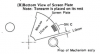
One thing I forgot, adjustment of the screen plate per this diagram...
upload_2022-12-27_7-54-55.png
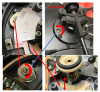
The diagram indicates the screen plate needs to be positioned 1.0mm away from the leg of the auto-mechanism. Unfortunately, it’s easier to adjust the screen plate when the lower auto-assembly is removed. The leg on the lower assembly that is removed to adjust the screen plater is larger (9mm dia. or 4.5mm radius) than the leg that it mounts to (6.8mm diameter or 3.4mm radius). So, the distance of the screen plate to the lower stanchion leg is, therefore, 2.1mm. I used a feeler gauge with three of the feelers all around 0.7mm thick and gently adjusted the screen plate while holding the tonearm on the rest. Turns out the screw that holds the plate in place is tight but not so tight that you can’t nudge the screen plate into place.
upload_2022-12-27_7-56-31.png
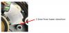
There is also a fine adjuster that can be adjusted from the top. It moves the sensor board back and forth just a little bit. Here it is with the sensor board removed:
upload_2022-12-27_7-58-31.png
 
On to the E and F sensor and associated LED.
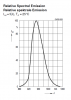
Here’s the datasheets for the LED and the phototransistors attached
You'll notice the LED is infrared, completely out of the visible range.
upload_2022-12-27_8-3-13.png

It would be nice to "see" if this LED is working. Enter the IPhone 13. Using my TV remote, I discovered that I can "see" the IR emitter with my IPhone, both front and back cameras. Let's try the turntable...
upload_2022-12-27_8-13-44.png

Success! LED is Lit!
 

Attachments

Last edited:
Nice work, using ALL your resources and some ingenuity to recognize their potential.

They are finicky mechanisms, to say the least.

As for unusual design, I believe other manufacturers offered "programmable" or "music select" turntables, but have no experience with their mechanisms.
 
Back
Top Bottom