• The move to the new server is done. There are some software and database maintenance updates in process. This has us passing the hat around to help out. We appreciate any donations. Seriously, even a dollar helps. The payment page may be found here - https://www.audiokarma.org/support.html

Starting a 400 restoration...thoughts??

BAH -- Power glide only had two gears and a TC. I'll take the 409 w/4-speed, and smoke your '27 and 'glide! Mo Power, Mo Power Mo Power!

Dave
 
Ha! I had a 63 Pontiac LeMans (glorified Tempest) with half a V8 and a two-speed powerglide transmission. I had it around 1980. A neighbor's father was a postman and bought it from a customer's estate.
That was a Delorean two door car and I could close the door with one finger.
Very cool, very comfortable, very easy to drive, very slow to accelerate, very poor mileage. I think the full V8 would have been cheaper to run because it wouldn't have had to work so hard to move two tons of automobile. That skinny driveshaft to the transmission in the rear would probably have had to be replaced routinely with a V8 though.
 
No need for phone books. '57 was the second year 6 way seat was available. Visibility is excellent in that car. The pedals are actually too close because of the floor design. I have to move the seat back on long trips.

Another tube wonder is the autronic eye headlight dimmer that works flawlessly.
 
Is that that sea shell looking thing up on the dash in the corner?? Always wondered what that was.

My '63 Impala in High School was bone friggin stock grocery getter. 283 2bbl, P.G., 2.79 rear, Dual's with glasspacks, NO A.C., AM Radio, HTR, and a back seat the girls would fight over! The Front seat wasn't too bad either (no floor shift). Cragar SS Mags, F70-15 Poly Glas tires. All White, Black Interior. It would get there, but not quick. I had faster VW Bug's.

I want another one! But I'd settle for a 61 or 62 also. OK I'm Desperate. I'll even take a Brookwood Wagon.
 
I am enjoying this car conversation! Who knew hot rods and tube amps went so well together?

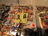
Attached are pictures of what I have done so far:

This is what still needs to be done/may be missing from the pictures:

-C93-96 need to be replaced with .068 Soviet PIO caps
-C69-70 need to be replaced with Soviet PIO caps
-screen resistors on the output tubes
-grid resistors 200k
-R101-102
-C63 with a film cap
-Daves bias supply design, mounted up underneath the chassis.

Everything was very easy so far, the most challenging was mounting the can electrolytics underneath the chassis. C52 got very BUSY, however I am pleased with the results. My goal was to keep all of the capacitors below the existing cans and not to have to start adding wires.

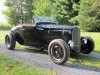
Anyone see anything that I missed or any horrific mistakes about to happen? There are a few items that are still coming in the mail and need to be added in (as listed above), however, I have a good feeling about the project so far. Let me know what you guys think... oh pics attached and speaking of hot rods, the last pic is my father's recently finished (minus the leather interior) 1929 Ford roadster. Every part is original ford with the parts cut off date of 1948. He started with a junkyard 32 ford frame 14 years ago. Engine is a full race merc flathead with a three two setup, 39 trans and a 1940's Franklin quick change rear. He did all the work and painting himself minus the engine machining. I got a 1927 Ford roadster in waiting for the same treatment.... :thmbsp:
 

Attachments

  • IMG_0323.jpg
    IMG_0323.jpg
    101.7 KB · Views: 41
  • IMG_0324.jpg
    IMG_0324.jpg
    98.7 KB · Views: 42
  • IMG_0334.jpg
    IMG_0334.jpg
    150.3 KB · Views: 42
  • IMG_0327.jpg
    IMG_0327.jpg
    112.2 KB · Views: 43
  • IMG_0312.jpg
    IMG_0312.jpg
    167.5 KB · Views: 38
Restoration looks great so far. Take your time.

Vintage cars and audio are a great team. Both have marque followers- Ford chevy, Cadillac, lincoln, etc. Or Fisher, McIntosh, Scott and on. Both will eat up your time and money. Both require you to have a hands - on basic knowledge of their systems to keep them running.

Summer is cars. Winter is audio season. Or rebuilding carburetors.
 
I am enjoying this car conversation! Who knew hot rods and tube amps went so well together?
.....

So, with vacuum tube car radios, how is your knowledge of vibrator driven high voltage power supplies?

Ford also used a wind up clock with a spring good for maybe 3 minutes. It was wound electrically.
 
Every car clock basically ran on the 3 minute wind. Westclox and Borg were 2 big suppliers. I prefer Borg movements for simplicity and reliability. Westclox tend to go into a winding frenzy and actually burn.

All I know about car radios is swap out the original vibrator for a solid state one. The originals get stuck and blow fuses. And they also make a lot of noise.
 
Betcha SHE goes into overdrive when the vibrator......UHHHHH Wrong Vibrator!!!! :D
 
I burst out laughing when the radio first acted up and my dad said I needed a vibrator. I said I wanted to listen to music not...

Funny thing is the one in the autronic eye never breaks. Only the one in the radio.

Apparently, this was a common problem back in the day. The original spark plugs were straight 4 4 ' s with no resistors. I had a plug wire go bad and all I got between stations was a tick tick tick.

I also never understood why the wonderbar concept never caught on in home audio. Pushing the bar to change stations is so neat but I also have the foot switch. People think the car is haunted when I tap the switch and the radio changes.

I'm really enjoying this thread but I'm going way off topic. Please forgive me.
 
Actually. I think Fisher had a wonder bar tuner with the 300 something, had 2 buttons on the faceplate and was the same chassis as a 200B...

Let us not forget the 57 Olds Super 88 with the J2 option... 3 dueces. :D
 
Actually. I think Fisher had a wonder bar tuner with the 300 something, had 2 buttons on the faceplate and was the same chassis as a 200B...

Let us not forget the 57 Olds Super 88 with the J2 option... 3 dueces. :D

Wouldn't some versions of the later Fisher "Tune O Matic" qualify as a "wonder bar"?
 
Al is correct -- in fact, there was one of the Fisher tuners he describes for sale not too long ago on the auction site.......

Dave
 
Auto Scan on the 500-TX/800-T and other Receivers (I believe) would be the closest analogy to the Wonder bar I can think of that FISHER had.
 
So as I am waiting on Fedex for my last shipment of goodies for the 400, I wanted the Fisher communities input on Ruskie PIO capacitors. I replaced the loudness control and phono ceramic caps with mojotone caps from "tubes and more" (loudness were the dijons and phono ceramics were the vitamin T) and was going to replace the stock euro coupling caps (I left the tone euro caps alone), and the phono dog turds also with vitamin Ts... but was lured the allure of the PIO caps our comrades in Russia made.

I bought four .068uf K42Y-2 (green) caps for the coupling caps and two .022 uf K42Y-2 caps to replace the phono dog turds (I also have 2 mojotones dijon film caps for the phono incase PIO on the phono is a bad idea). They were way cheaper than the mojotones and I have heard nothing but positive reviews on K42s and K40 caps.

I know many people prefer the K40's over the K42s, my question is has any Fisher 400 fans used K42s in a similar fashion as I am planning? Were you pleased with the results or did it alter the sound too much? Is there a sweet combination of K40s and K42s in Fishers that I should consider?

I don't want to greatly alter the Fisher sound, just improve on it. I gotta get stereo guys advice on this, I can't sift through the opinions of guitar players on Russian Caps. We just have different preferences in sonics....
 
Last edited:
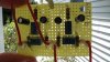
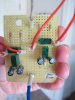
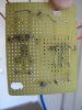
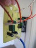
So I got Dave's balance/bias supply together last night and I want to make sure I have it wired properly before I install it on the chassis.

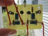
Question 1: What is the connection configuration on the trim (bias to balance) pots? Currently (see pictures, starting from the top of the board) I have the 10k r connected to the 3 pin of the trim pot. Pin 2 and 1 soldered together and wired to pin 2 of the balance pot and wired to pin 1. Pin 3 soldered to the 15k r and the "out" red wire. Green is ground. Disregard the "V" labels, they are coming off. Does this configuration sound correct?

Question 2: The 25v heater supply connection, is that the white wire coming off of C60 capacitor? Do I need to tie this into the bias circuit?

Question 3: I also have a second shorter white wire that connected the old grid return resistors (R117-R120), what do I do with this wire?

Still waiting on the PIO caps...

Thanks for the help!

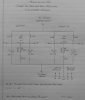
Last pic is Dave's schematic that he posted on the original bias thread and which I used to create this circuit. Thank you for sharing this with us Dave!
 

Attachments

  • MVI_0380.jpg
    MVI_0380.jpg
    59.5 KB · Views: 30
  • IMG_0381.jpg
    IMG_0381.jpg
    67.2 KB · Views: 34
  • IMG_0383.jpg
    IMG_0383.jpg
    64.9 KB · Views: 33
  • Dave's 800C Bias Supply.jpg
    Dave's 800C Bias Supply.jpg
    101.4 KB · Views: 32
Last edited:
Orient your board to match Dave's diagram.
A,B,C,D are your tube bias leads. They go to each free end of the new Grid return resistors. Remove any old wires, back to their sources. (Q3)

"TO 25V Heater Supply" goes to Directly to the NEGATIVE SIDE of the DUAL BIAS Cap. (Remember this is a Negative Voltage supply.) Remove the old parts, R34, R35, C42 (I'm using the 48001 and up manual.) I don't see this particular lead on your board. (Q2) But I can't make heads or tails of your board on the back. It looks to me that the inner caps/resistors aren't conected to the + supply.

The ground lead goes to a convenient chassis ground.


Larry
 
Thanks Larry for your response. I figured if you couldn't figure out what was going on from my pics, then I should redo the board so....attempt #2 and I think I got it. My circuit is the exact configuration as Dave's diagram (except the right circuit is shifted up to avoid my mounting studs). Added all of the wires you suggested and removed the cap and resistors you suggested as well. It is not soldered yet...waiting for the blessing from the AK community haha

Also, sanity check on C56 (black cardboard can cap), when I disconnected and mounted the terminal strip for the 220uf replacement cap, I mounted and grounded the strip to the the old C56 ground tab. It seems that this grounding/negative lead tab is not connected to the chassis or any other ground on the amp. I did the same exact thing; mounted my new ground and terminal for the replacement cap (see pic). Is this correct? Seems odd that this is the only electrolytic cap thats negative lead is not connected to the common ground.

Thoughts anyone? Any pending disaster?
 

Attachments

  • IMG_0403.jpg
    IMG_0403.jpg
    61.2 KB · Views: 17
  • IMG_0404.jpg
    IMG_0404.jpg
    57.4 KB · Views: 18
  • IMG_0405.jpg
    IMG_0405.jpg
    38.4 KB · Views: 14
  • IMG_0406.jpg
    IMG_0406.jpg
    45.5 KB · Views: 17
  • IMG_0408.jpg
    IMG_0408.jpg
    128.3 KB · Views: 23
  • IMG_0411.jpg
    IMG_0411.jpg
    60.2 KB · Views: 20
The Cardboard cap is supposed to be ISOLATED ELECTRICALLY from the chassis. In other words, not connected in anyway thru either the ground or hot leads. It's part of the Voltage doubler circuit (C56, C57C.) C56 and 57C are daisychained, if you will to increase the voltage above what the transformer is capable of normally (hence the "VOLTAGE DOUBLER" name). Ground that anywhere, and you end up with a SMOKING PILE, not fit to be used as a doorstop.

You can mount the Terminal strip to the chassis. Just don't mount the cap (Neg or POS) to the ground lug on that strip as it has to float above ground potential. Actually the strip is mounted safer that way (directly to the chassis), as there is more strength in a metal to metal joint than a metal to phenolic joint.

Better on the BAL/BIAS board. Go ahead and solder it all up.
 
Back
Top Bottom