• The move to the new server is done. There are some software and database maintenance updates in process. This has us passing the hat around to help out. We appreciate any donations. Seriously, even a dollar helps. The payment page may be found here - https://www.audiokarma.org/support.html

Starting a 400 restoration...thoughts??

So I finished the 400 yesterday (minus the PIO caps from russia, I just put some mojotones and the old Euro cap coupling caps in for the meantime) and slowly brought it up on the variac. I got to about 90v when I realized that there was no negative voltage on the output tubes and none on the white wire coming off of the dual cap power supply to the IBAM. So I checked the dual power supply and it is showing 0 voltage :sigh:. Checked the wiring of the bridge rectifier, the redone can caps and everything seems to be where is should be...

Everything else went fine with the start up, phase inverter adjustment showed the left channel to be perfect and the right channel way off. Larry's adjustment instructions from his 400 restoration were GREAT and they are now exactly where they need to be.

The 7868's didn't red plate or anything at 90v and I shut it down as soon as I realized there was no negative voltage going to them...

Q1: Any thoughts on what could be the culprit here?

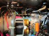
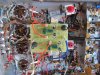
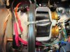
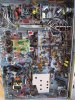
Attached are pictures focusing on the power supply area, if there is a specific reading or close up someone would like to see to reveal the possible culprit, just let me know and I will gladly provide them.

Q:2:Is there any instructions for a newbie on how to dial in the IBAM board for the first time? Specifically how to balance and then what the bias level should be for the output tubes.

Thank you in advance...we are so close to finishing this thing!!!!
 

Attachments
  • IMG_0412.jpg
    IMG_0412.jpg
    138.5 KB · Views: 30
  • IMG_0419.jpg
    IMG_0419.jpg
    87.9 KB · Views: 29
  • IMG_0423.jpg
    IMG_0423.jpg
    73 KB · Views: 28
  • IMG_0413.jpg
    IMG_0413.jpg
    122.5 KB · Views: 31
  • IMG_0417.jpg
    IMG_0417.jpg
    118.6 KB · Views: 31
Last edited:
Did you reconnect the 15 ohm power resistor back up to the positive terminal of the silicon bridge rectifier? I can't see that terminal clearly enough to determine this.

Dave
 
What Dave said. Then take voltages on the DBT until you get it sorted out. Start at the -(NEG) terminal of the Rectifier and work your way across each joint you made. Also check the + side of the rectfier.

Once you get that sorted out and Neg voltage to the tubes then we'll go over the BAL/BIAS pot settings for initial startup.
 
Ok, I checked my work. The 15 ohm resistor is properly connected and all other rectifier/bias cap connections are correct and the joints are good. The only issue I found was that I corrected was the negative leads on the dual cap were connected and grounded to the chassis. The positive side of the one cap was also connected at the original location of the old cap on the terminal strip near the antenna connection. I can see now that this was very incorrect :nono: as I essentially grounded the positive and negative leads on the bias cap...

Removed the chassis ground from the negative leads of the can and kept the ground on the positive lead. Turned it on at 80 v input, the white negative wire on the bias board is reading -0.001 vdc.

The postive lead of the dual can cap that the 15 ohm resistor /+ of the bridge rectifier is connected to is reading 20.6vdc and the other postive lead on the dual cap (the only chassis ground now) is reading 0.000VDC.

Something is still not right here....

Do you think having both the positive and the negative lead on the one can grounded fried the cap requiring it to be replaced?
 
Here is some close ups from the power supply section...
 

Attachments

  • IMG_0428.jpg
    IMG_0428.jpg
    80.7 KB · Views: 21
  • IMG_0429.jpg
    IMG_0429.jpg
    68.9 KB · Views: 20
It's possible you more likely fried the rectifier. Take voltage readings directly off the rectifier. If 0.0v on both replace it. You can replace the caps too if you want but I don't think you hurt them, else they'd be bulging or vented.
 
The other likely possibility is that the 15 ohm resistor could now be toast, since shorting the negative of the filter caps to ground basically placed the 15 ohm resistor directly across the output of the bridge rectifier. I would check it first before replacing anything else. When you check it, be sure to remove one phono preamp tube, and one line or tone amp tube. Otherwise, the heaters in these tubes will give you a false reading.

Dave
 
Thanks guys, I would have never known to check these items!

Ok, so when the 15 ohm resistor was connected in circuit (with the tubes Dave instructed were removed), I could get no resistance reading at all, when I disconnected the 15 ohm resistor it reads 9.14 m ohms. I definitely think this resistor is fried. Also, I disconnected the bridge rec and I am getting leakage across one of the AC leads. So new bridge and 15 ohm resistor...

Thinking back to my initial start up, before I realized there was no negative volts (around 90v input), I did notice the one dual cap (closest to the front of the amp, but not the one closest to the rear) and some of the 40 uf caps from the 4 section multi can replacements were warm/hot to the touch. There are no visual indications of damage (bulges etc) on the caps, should these be removed and checked with my DMM?

Any thing else I could have fried in this gaff? The input tubes maybe?

I will swing by my component supply store and see if they have the items I need on monday and hopefully have good news monday night on negative voltage.

Thanks for your help!
 
If you still have the original electrolytic can caps in place, and they are running warm/hot, then they need to be replaced immediately. A good can cap will generate no heat of its own, although they will absorb heat from surrounding heat producing items. When they start to generate their own heat however, they are breaking down internally causing current draw through the caps, and the resultant heat that produces. This has nothing to do with the error in wiring in the heater/bias supply.

The 15 ohm resistor is definitely fried as suspected, and needs to be replaced. Regarding the bridge however, when you say you get leakage across one of the AC leads, can you elaborate on this?

Dave
 
I did a quick google search "how to tell if a bridge rec is bad" after your responses and one of the ways the site said was a sign of a diode not working was to connect the DMM leads to the each AC pin and have the DMM on the resistance function. Any reading of resistance would indicate leakage and the diode not working. When I connected my DMM leads to the AC pins, there was a fluctuating amount of resistance on the DMM read out. I don't know if this is the proper way to check a rectifier haha this is new territory for me!

Great insight on the caps, the old can caps are all disconnected and in place and I mounted new caps in the chassis. Things are crowded in there and it is possible the 3 of the 4 caps of C52 were absorbing the heat from the closest dual can cap that is directly below (the amp was standing on its side, and hot air rises) the C52 caps....

I think at this point I will replace the known culprit (15 ohm R) and the bridge Rec. and take it from there with a watchful eye.

Thanks for your help Dave. I learn so much when I make mistakes!!
 
Likely, your bridge is still good. Modern DVMs do a poor job of checking diodes when using a resistance function, as they don't place enough voltage across the diode to properly trigger it -- unless it specifically has a "diode check" setting. This is basically an ohms setting as well, but places more voltage across the device (diode) being tested. This is why the setting exists -- but it's on modern DVM's only. Older analog ohm meters sent enough current through the device it was testing so as to properly trigger a diode being tested on the ohms function. Therefore, they didn't need a diode test setting. If your dvm has such a setting, try use it before condemning the bridge.

Dave
 
Thanks Dave, after reading your post and investigating all the features of my Fluke 110, it seems I have a diode tester function so....the bridge passed the new set of tests and appears to be good for another try.

I'll pick up a 15 ohm resistor today and give this bias supply another shot!

Thanks!

-Drew
 
Great!

I had a sneaking suspicion that the bridge would be OK. Silicon devices rarely fail in an "open" or "with leakage" fashion: They simply short and become a wire. When that happens, then other things happen, like fuses blow. In your case, by wiring the 15 ohm resistor across the output of the bridge, the circuit was trying to conduct about 2 A of current, which would have been naturally limited to a value somewhat below this level by the resistance of the transformer winding, but was still an excessive current level anyway. But it only would have lasted for a very short while, as the resistor would have been trying to dissipate about 60 watts during this time, but is only a 7 watt device. Therefore, it burned open rather quickly, which removed the load on the bridge and transformer, but also left no voltage going to your tubes. The bridge almost surely took this abuse in stride (likely still flowing less than rated current flow), dumping all available current into the resistor, killing it.

You'll have it going in no time!

Dave
 
Great to hear and your explanation makes allot of sense. When I fired this up the first time I actually put a 2 A fast blow fuse in (instead of the 3.2 slow blow) just in case I made a mistake like this. So I guess its good that there was never enough draw to blow that out.

So if the bridge came out of this unscathed, do you think my dual can power supply caps are also ok? I know one was putting off heat (the one directly connected to my burned up 15 ohm R). If I am getting a new R today, should I just replace these as well to rule out any other possible variables to my problem?

-Drew
 
The caps went through the entire event in ignorant bliss, having no idea that the event even occurred.

There really is no way that the one cap was generating any heat of its own in this event. Most likely, it was simply acting as a heat sink for the poor power resistor that was trying to get rid of its extreme heat any way it could before it burned open. Based on the wiring misque, theory says only the resistor would be damaged, with the rest of the relevant components just spectators to the event. Replace the resistor, and you should be good to go.

Dave
 
We have negative voltage!!

At 60 v input we have -10.68 off the white wire coming into the bias control.

A HUGE thanks to Dave and Larry for helping me through this!

I have it up to 90v now and the Grado headphones & computer plugged in....sounds amazing!!

So I am going to try and tackle the balance/bias tonight, any tips/instructions would be greatly appreciated!

Thanks!!!
 
Last edited:
GO SLOW, Take your time, Double Check all your Joints.

The BALANCE pot (top one) gets centered. The BIAS gets set for MAXIMUM Negative Voltage. That way you don't put the tubes into a China Syndrome on startup.

1.) Balance the pair by placing your meter(set for DC Volts) leads on the test points for each of the pair tubes. Say you are doing V9-V10. Put Red on V9 and Black on V10's (or the other way around it don't matter here). Then use a jewelers screwdriver and tweak the BALANCE pot back and forth in tiny movements to get to zero volts.
Remove the probes. and repeat for the other pair.

2.) BIAS. Clamp the BLACK METER PROBE to a CHASSIS GROUND. (The side of the chassis is fine). Set your meter for DCV. Red probe pin 9 to get your plate voltage. Multiply the plate voltage by .032 (320mv) to get watts. You want ideally between 14.5 and 15.2W (75%-80% of max). Adjust your math as needed to get in range. It may be as high as 34ma(340mv) to 36ma(360mv). Once you figure the math, Red probe to one of the test points(black stays connected to chassis) and adjust the BIAS POT(bottom one) until you get the mv you calculated. REPEAT for the other pair.

You're done! Kick back and Enjoy it.......AFTER you've cleaned up the mess to SWMBO's satisfaction. :D SWMBO is "She who must be OBEYED!"
 
Last edited:
Sorry for not posting! I have been away for the week. Ok, so I followed the bias instructions...perfect. The balance was super easy and the tubes are staying balanced! I had a 9 pin reading of 385 VDC on all tubes. My calculations came out to .038 and that is what I adjusted the bias on both sets.

Readings
V17
pins
1 350vdc
2 -15.82 vdc
3 .380 vdc
4 2.99 vac
5 3.0 vac
6
7
8
9 379.8 vdc

V16-v14

Very similar readings as v17 except pin 2 is 16.6 (both v16-v15) and v14 is 16.49 for pin 2.


Do these readings look good?

I am just blown away by this receiver. Everything just sounds so lively, accurate and most of all fun to listen too. Dead quiet, no fuzz or hum noises. The phono stage is wayyyy better than before or my stock kx-100.

My only concerns are that the stereo still sounds crazy. I feel wants to sounds great, but it is just not right. Does something else need to be adjusted/replaced in this area?

A huge thanks to Larry and Dave and the others who offered their advice on this project. I will post a video on youtube once I get everything fine tuned.
 
Congrats! The number look good, although the overall AC voltage to the unit appears to be slightly low.

When you say that "the stereo still sounds crazy" -- what do you mean? Is this on all sources, FM mono, or just FM Stereo reception?

Dave
 
Back
Top Bottom