• The move to the new server is done. There are some software and database maintenance updates in process. This has us passing the hat around to help out. We appreciate any donations. Seriously, even a dollar helps. The payment page may be found here - https://www.audiokarma.org/support.html

Starting a 400 restoration...thoughts??

Congrats! The number look good, although the overall AC voltage to the unit appears to be slightly low.

When you say that "the stereo still sounds crazy" -- what do you mean? Is this on all sources, FM mono, or just FM Stereo reception?

Dave

Oh man, I meant "the FM stereo still sounds crazy":D Everything except the FM stereo sounds phenomenal... The FM stereo sounds like ocean wave like music and I can never lock into a station. It sounds like I am always in between a station. FM mono sounds great and I am very happy with that, however, I would love to get the FM stereo sounding nice. We have a VERY NICE jazz station in our area.

As for the AC voltages, the input was 117 v off of a variac, could that be why my AC numbers are low? Wall volts here is about 120-123v...I was planning on always running the 400 off of my variac at 117v, so I biased it with that in mind.

What numbers would you like to see? Any thoughts on how to get there?

Thanks for the help Dave!
 
Agree on the overall AC voltages. Pin 1 should be close to 365 or so. Pin 9 should be about 405.

Couple of questions;
1.) What is/was the input voltage from the wall when you took the above #'s? (We were typing at the same time so 117)
2.) What are the voltages (AC) on the transformer sections?
3.) Have ALL of the CAN CAPS been replaced?
4.) Did you check the power supply resistors between the can cap sections for ohms + / - 10%? If out of spec, did you replace them?

Use the 48001 and up manual for voltages as it's the highest numbered manual available.

By crazy do you mean somewhat distorted in FM STEREO, as opposed to MONO? What about the other sources, (Phono, Aux, Tape in). I'm thinking the Stereo separation pot has been cranked to on side or the other on the MPX. There is a pot between V101 and V102 that is part of the MPX Alignment setup and should only be adjusted during the alignment. BUT having said that, you can visually check it, and see if it's near center. Look at it and tell me what you see.
 
Last edited:
Either that, or the 1 uF cap in the MPX unit has gone south. Larry, do you have a pic of that cap you could show him?

Dave
 
The cap is on the LEFT SIDE of the pic about 1/2 way down. Circled. 1uf 350V. Ratshack DOES NOT have this cap.
MPX CAP 400.jpg
Use Nichicon TVX2V010MAD Mouser # 647-TVX2V010MAD in AXIAL, or 647-UPW2V010MPD in Radial.
 
Last edited:
Agree on the overall AC voltages. Pin 1 should be close to 365 or so. Pin 9 should be about 405.

Couple of questions;
1.) What is/was the input voltage from the wall when you took the above #'s? (We were typing at the same time so 117)
2.) What are the voltages (AC) on the transformer sections?
3.) Have ALL of the CAN CAPS been replaced?
4.) Did you check the power supply resistors between the can cap sections for ohms + / - 10%? If out of spec, did you replace them?

Use the 48001 and up manual for voltages as it's the highest numbered manual available.

By crazy do you mean somewhat distorted in FM STEREO, as opposed to MONO? What about the other sources, (Phono, Aux, Tape in). I'm thinking the Stereo separation pot has been cranked to on side or the other on the MPX. There is a pot between V101 and V102 that is part of the MPX Alignment setup and should only be adjusted during the alignment. BUT having said that, you can visually check it, and see if it's near center. Look at it and tell me what you see.

Ok, to answer your questions Larry and Dave,

#1- 117v
#2- I will have to pull the bottom off to get these values, what am I looking for here?
#3- All can caps are replaced with new caps and of greater value/voltage (basically I copied Larry's thread here).
#4- The only resistors associated with the can caps that I did not replace (or check...) were the carbon comp on C 52. I reused them without thinking about it.

In the MPX section, I attached a picture of the blue trim pot, does not seem to be centered to me...this is the only design flaw on this Fisher that I can think off. Any time you grab the chassis, you risk bumping this adjustment...

So the electrolytic cap on the MPX section was replaced with a film, half of the dog turds were replaced (47uf) and the other half I forgot to order. The one large cap C32 .1uf, I did NOT replace. Maybe thats the culprit here...
 

Attachments

  • P9280543.jpg
    P9280543.jpg
    55.1 KB · Views: 22
The cap is on the LEFT SIDE of the pic about 1/2 way down. Circled. 1uf 350V. Ratshack DOES NOT have this cap.

Use Nichicon TVX2V010MAD Mouser # 647-TVX2V010MAD in AXIAL, or 647-UPW2V010MPD in Radial.

attachment.php

Hmm yea, replaced that one you circled, from your picture if you move up (towards the face of the amp) just past the orange wire there is C32 hiding behind 2 resistors. Thats the one I did not replace (I thought it was a huge wire wound resistor for the longest time!)
 
Your culprit is the pot. Set it for just shy of center on the side where it is now. Do it while it's playing. You'll notice the aggravating distortion back off fairly quick.

You can probably leave C32 as is.
 
Yep, Larry's call was correct. A properly functioning MPX unit will NEVER require an adjustment at either extreme of rotation for the Stereo Separation control.

Glad its working well for you now!

Dave
 
Great Job.

I'm just wondering if this is common between all the higher numbered 400's (say above 50000) as the last two I did were high end numbered and their plate and screen voltages were similar to yours. Might be that AX transformer. And then FISHER didn't document the change.
 
Hmm, yea mine is a 77,XXX. Are the measurements alarming or OK and just different than the lower SSN models you are familiar with?
 
Last edited:
The plate and screen voltages are 25 and 15volts lower than spec(according to the manual), but consistant with the few later model 400's I've done in the last year. If you've checked the power supply resistors (between the can sections) and they are ok, then I wouldn't worry about it.
 
hi fishermen
maybe it's been treated elsewhere, my mistake but if someone can help me with identifying tubes dispatch in preamp section and especially the tuner FM stereo ones
incidentally, which brands/series are considered better for each preamp section?
thanks in advance
phil
 
Late model 400's (with 6 Tuner Tubes.) If below 48001 serial #, unit has 5 tuner tubes, adjust upper tube numbers down by 1.
Multiplex tubes are V100-101-102
Tuner tubes are V1 thru V6
Stereo Beam Indicator is V7
PHONO are V8-V9
Voltage and tone amp tubes are V10-11
Phase Inverter are V12-13
Output Tubes are V14-15-16-17

Fisher used both Telefunken (early) and Sylvania(late) in them (branded as FISHER). I've used everything from RCA to matsushita's in mine. No real favorites. As a disclaimer no one's ear's are the same and you may not like what I have in my rigs, or I may not like the tubes in someone else's. I leave that up to your ears.
 
There is little that tubes contribute to the "sound" of the FM tuner section, or even in the stereo multiplex section, either. Clean sound from the tuner section depends primarily on a good alignment, while clean sound with good separation from the stereo multiplex section also depends on a good tuner alignment, and of course good alignment of the multiplex section as well.

Dave
 
my number is 14311D which seems to be an early model
down by 1... hum, sorry...:confused:
what's the correct dispatch then?
thanks in advance
phil
 
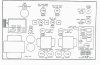
In your case V1 thru V5 are your tuner tubes. You have the EARLY Version. Only 5 Tuner tubes

EARLY (10001-47999)
400 Tube layout 10001 to 47999.jpg

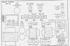
Vs the late version which has 6 tuner tubes.

LATE (48001 and up)
400 layout 48001 and up.jpg
 
Last edited:
Provided you can find one. If you can't then a 6hr6 or 6AU6 can sub (with some degradation) until you do.

EDIT 12-22-15: I've found that the 6AH6 is comparable to the 6HR6 and 6HS6. I've been using it in place of 6HR6 and 6HS6 in 400's, and all of my Custom Electra Tuner's without problem or degradation of signals. The 6AH6 is CHEAP too compared to the almost non-existant 6HR6 and 6HS6.
 
Last edited:
Back
Top Bottom