

You are using an out of date browser. It may not display this or other websites correctly.
You should upgrade or use an alternative browser.
You should upgrade or use an alternative browser.
SX-1000TD Odd problem - hoping for some help
- Thread starter spark1
- Start date

merlynski
Curmudgeon Electronicist
Yes, one side of R41 is signal, one side is ground.
For a home made signal tracer you need a probe, with a dc blocking cap in line to listen to various point along the signal path, and some kind of audio amp (with an Aux or line level input) and a speaker to amplify it to audible levels. The cap needs a high enough voltage to never be exceeded by any dc on any circuit you measure, I suggest 100v minimum. Film, not polarized like electrolytics.

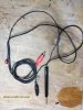
Plug it in to the input of the small amp, adjust volume as needed. I works great to compare the same point in a signal path between left and right channels, just feed the same signal into both.
For a home made signal tracer you need a probe, with a dc blocking cap in line to listen to various point along the signal path, and some kind of audio amp (with an Aux or line level input) and a speaker to amplify it to audible levels. The cap needs a high enough voltage to never be exceeded by any dc on any circuit you measure, I suggest 100v minimum. Film, not polarized like electrolytics.
Plug it in to the input of the small amp, adjust volume as needed. I works great to compare the same point in a signal path between left and right channels, just feed the same signal into both.

Yes, one side of R41 is signal, one side is ground.
For a home made signal tracer you need a probe, with a dc blocking cap in line to listen to various point along the signal path, and some kind of audio amp (with an Aux or line level input) and a speaker to amplify it to audible levels. The cap needs a high enough voltage to never be exceeded by any dc on any circuit you measure, I suggest 100v minimum. Film, not polarized like electrolytics.
View attachment 2132729
View attachment 2132734
Plug it in to the input of the small amp, adjust volume as needed. I works great to compare the same point in a signal path between left and right channels, just feed the same signal into both.
Cool. This, plus the ability to identify signal path, will be handy.
First, let me say that I have difficulty with this unit figuring out R and L once I get past the amp board. Neither the bias pots nor the R40/R41 resistors are marked with any identifier that helps me, and the emitter resistors are a long way from the output transistors (and on underside of board). Very difficult to trace wiring.
In fact, when initially setting bias, I had to experiment to find the right resistors to measure across. I ended up using the first and third .7 ohm resistors of the four to to right in the pic, below. Each pair of these are connected in series across the coupling caps. I am assuming these are the emitter resistors.
Interestingly, I seem to be able to also measure/adjust bias voltages measuring across the single .7 ohm resistors that are between the negative terminals of the filter caps and the terminal strip upon which the bias pots are mounted.
Very confusing...hard for me to translate the schematic to the physical layout.
In any case, my lack of confidence about L vs R bias measurement does not appear to be an issue, since both seem to be holding steady. They start out lower than where I set them, but after 10 mins get within a mV or so. One did show some up and down fluctuation of 3mV both directions once in a while, but after about 30 minutes this ceased. I don't think this could be the source of the problem, as it never drifts below the recommended 20mA (I have bias set to 30mA/21mV)
Center voltage was very steady, from initial power up until I powered down about 45 min later...variance in either channel was no more than .2V.
DC voltage across R40 and across R41 was similar...fluctuating between 45-50mV on what I think is R40, and between 50-55mV on what I believe to be R41. This was pretty much the case from initial power up until power down.
BTW, I assumed that the two red, tubular resistors you can see between the emitter resistors (?) and the transformer are R40 and R41. They seem to be in the right place in the circuits, and they are 330ohm.
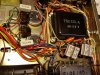
In fact, when initially setting bias, I had to experiment to find the right resistors to measure across. I ended up using the first and third .7 ohm resistors of the four to to right in the pic, below. Each pair of these are connected in series across the coupling caps. I am assuming these are the emitter resistors.
Interestingly, I seem to be able to also measure/adjust bias voltages measuring across the single .7 ohm resistors that are between the negative terminals of the filter caps and the terminal strip upon which the bias pots are mounted.
Very confusing...hard for me to translate the schematic to the physical layout.
In any case, my lack of confidence about L vs R bias measurement does not appear to be an issue, since both seem to be holding steady. They start out lower than where I set them, but after 10 mins get within a mV or so. One did show some up and down fluctuation of 3mV both directions once in a while, but after about 30 minutes this ceased. I don't think this could be the source of the problem, as it never drifts below the recommended 20mA (I have bias set to 30mA/21mV)
Center voltage was very steady, from initial power up until I powered down about 45 min later...variance in either channel was no more than .2V.
DC voltage across R40 and across R41 was similar...fluctuating between 45-50mV on what I think is R40, and between 50-55mV on what I believe to be R41. This was pretty much the case from initial power up until power down.
BTW, I assumed that the two red, tubular resistors you can see between the emitter resistors (?) and the transformer are R40 and R41. They seem to be in the right place in the circuits, and they are 330ohm.
Last edited:
merlynski
Curmudgeon Electronicist
Well, you are ahead of me in the parts identification area. You actually have the unit in front of you. I have never seen one or worked on one. I work from schematics and Service Manuals to figure out the electronics problems. Many here on AK have much more 'hands on' experience than I will ever have with home audio equipment. The photo helps immensely, and your logic makes perfect sense to me.
When you get the signal tracer built you should be able to hear the difference you describe along the signal path, by comparing left and right.
Did the distortion occur in this last session? Does it happen only when audio is playing, or does it occur as the units sits and warms up, and then is immediately heard when the audio input is switched on?
The latter. Occurs after warm up, regardless of whether signal is applied initially or after warm up.
I assume the smallamount of DC on the 330ohm resistors is nothing to worry about?
I wont be able to get out and buy a spare probe for a few days...bad, bad weather here.
Have everything else I need.
In meanwhile, I'm going to try to confirm right and left sides of each board by lifting inputs/outputs with signal only one one channel.
Have any ideas on how to identify which pair of output transistors is R vs L? Same question for bias pots, filter caps and coupling caps?
Doohhh. Once I confirm R vs L on main amp board, I can use the centering trimmers mounted on that board to identify R vs L output pairs.
Question remains for bias trimmers, filter caps and coupling caps.
FYI...ignorance is not bliss!
Sure appreciate the help.
Question remains for bias trimmers, filter caps and coupling caps.
FYI...ignorance is not bliss!
Sure appreciate the help.
Last edited:
merlynski
Curmudgeon Electronicist
Too soon to tell, but swapping would not hurt anything, and might be the answer. Are they all new transistors?One other thing...is it worth swapping the outputs, or have they been eliminated as likely source?
Once I know which transistor is which I mark on the heatsink next to them their ID. I have some metallic Sharpies that work great on black anodized aluminum.
merlynski
Curmudgeon Electronicist
The latter. Occurs after warm up, regardless of whether signal is applied initially or after warm up.
I assume the smallamount of DC on the 330ohm resistors is nothing to worry about?
I wont be able to get out and buy a spare probe for a few days...bad, bad weather here.
We were -18ºF last night!
merlynski
Curmudgeon Electronicist
We got about 4 inches of snow. We did not lose electricity this time, but my water heater pilot is out.Damn. I thought -9 was bad.
Rolling blackouts by electrical utilities here today. Thank goodness we have four fireplaces (converted to gas).
We have wood stove in the basement, but neither of us is very good at getting up and down the stairs.
You can use a stiff piece of solid copper wire for a probe, don't need anything fancy. Insulated except at the tip.
Got some romex. I will work on this today.
merlynski
Curmudgeon Electronicist
Yup, that works perfectly.I have some .1uf 630V caps...ok?
I've got a little t-amp someone gave me a long time ago. Going to use it for the signal tracer, but need to order a power suppy for it.
Going to research signal generator apps for my phone tonight. Got the cable built. Used 16 gauge wire for the probe....wish I hadn't, as it is not as flexible as I would like. 24 gauge for the ground. May build another one using 24 gauge for both.
The 14 gauge solid romex is going to work nicely as a probe. Sharpened the end with a Dremel grinder.
Thx for motivating me!