

You are using an out of date browser. It may not display this or other websites correctly.
You should upgrade or use an alternative browser.
You should upgrade or use an alternative browser.
SX-1000TD Odd problem - hoping for some help
- Thread starter spark1
- Start date

merlynski
Curmudgeon Electronicist
You are describing the problem as it losing bass, being thin and weak? That points at S7. Measure the contacts with your ohmmeter on as low as possible a scale. Compare left and right. That contact has to be closed to defeat the low filter (0.2µF cap)
EDIT: it could be a bad track on the balance pot . . .
EDIT: it could be a bad track on the balance pot . . .
Last edited:

You are describing the problem as it losing bass, being thin and weak? That points at S7. Measure the contacts with your ohmmeter on as low as possible a scale. Compare left and right. That contact has to be closed to defeat the low filter (0.2µF cap)
EDIT: it could be a bad track on the balance pot . . .
Even though it sounds good on the balance pot tabs?
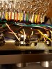

View attachment 2138395
Just to be clear, signal is good at the green arrow, bad at the orange arrow. How is it at the blue arrow?
Good at green. Bad at orange. Working to check at switch.
Well, I think I tested correctly. I checked signal at the middle pins of the switch. These are the same pins to which the wires feeding the balance control are attached (as well as one leg of the mylar .2uf caps)...I assume therefore I am hearing the signal being passed FROM the switch.
Both sound good.
This means it is the pot, correct? If so, that is bad news.
Both sound good.
This means it is the pot, correct? If so, that is bad news.
Last edited:
merlynski
Curmudgeon Electronicist
The signal goes through the switch when it is closed, through the cap when it is open.
F5 Faderlube, if the wiper contact or surface of the track are dirty.
It still could be a problem on the Main Amp input stage loading the output from the pot.
You are in the right area, keep looking. I gotta hit the sack, back tomorrow
EDIT: more
F5 Faderlube, if the wiper contact or surface of the track are dirty.
It still could be a problem on the Main Amp input stage loading the output from the pot.
You are in the right area, keep looking. I gotta hit the sack, back tomorrow
EDIT: more
Last edited:
merlynski
Curmudgeon Electronicist
The pot is not likely to exhibit the symptoms you describe.
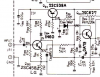
OK, next step is to look at the input stage of the Main Amp.
Measure dc volts across C802, noting that the voltage polarity across it matches it marked polarity. Did you change C802? What with?
Measure dcv at the base of Q802 for +9.8vdc (schematic is badly marked) and the emitter as +9.2vdc, the collector as +17vdc. Did you change Q802? What did you replace it with? Q812 as well?
Measure dcv on the emitter of Q812 for +22vdc, and the base as +21.4vdc.
DC voltage drop across D804 should be about 0.2vdc (its a germanium diode).
The pot is not likely to exhibit the symptoms you describe.
View attachment 2138702
OK, next step is to look at the input stage of the Main Amp.
Measure dc volts across C802, noting that the voltage polarity across it matches it marked polarity. Did you change C802? What with?
Measure dcv at the base of Q802 for +9.8vdc (schematic is badly marked) and the emitter as +9.2vdc, the collector as +17vdc. Did you change Q802? What did you replace it with? Q812 as well?
Measure dcv on the emitter of Q812 for +22vdc, and the base as +21.4vdc.
DC voltage drop across D804 should be about 0.2vdc (its a germanium diode).
Good morning. I'll head down to the workshop in just a few minutes and do those measurements.
I did play around a bit with the pot. Interesting to see how it works...50K pot, but each side (gang?) only ranges from near 0 to around 25K. I would guess that this is how it is supposed to work.
Hope all is well in CO today. Cold snap has finally broken here...may get some winter kayaking in next week!
Measurements are a bit tricky...I have to flip the board to identify the component on the top side (they are not marked), mark them on the foil side, then screw the board back down and do the measurements from foil side.
Here is what I have so far, with unit warmed up:
DC across C802 = 10.75V (was 9.6 when cold)
DC across C801 = 9.12V (cold and warm)
DC across D804 = .514V
DC across D803 = .430V
DC at Q812: Base = 26.45V, Emitter = 26.35V
DC at Q811: Base = 22.06, Emitter = 21.8V
I have to figure out how to get at Q802...it is blocked by an insulation tube containing foil-side mounted components. It and its counterpart were replaced with 2SC1815s.
Since the diode measurements are much higher than expected, I will go back and reconfirm I measured at correct points when I figure out how to get at Q802.
Now that unit is even more warmed up, Base voltage on Q812 has increased to 27.76V. Emitter increased to 27.41.
Forgot to mention that C802 was replaced (10uf Nichicon). All caps on this board are new, except the 2 bipolar (waiting for parts order to get here).
Forgot to mention that C802 was replaced (10uf Nichicon). All caps on this board are new, except the 2 bipolar (waiting for parts order to get here).
Last edited:

petehall347
the brandy coffee man
DC at Q812: Base = 26.45V, Emitter = 26.35V
looks dead .. would be better if you could measure right across b to e . to be sure ..this should be 600mv