• The move to the new server is done. There are some software and database maintenance updates in process. This has us passing the hat around to help out. We appreciate any donations. Seriously, even a dollar helps. The payment page may be found here - https://www.audiokarma.org/support.html

SX-1000TD Odd problem - hoping for some help

Well, the Mouser order I placed last week (Thursday) still hasn't even been picked. With the weather and covid, I would guess it won't get here until the weekend, at best.

So, will go ahead and swap the outputs while waiting. Worth a try, I guess...especially since nothing obvious showed up in the earlier measurements.

Ordered a power supply for the little T amp which will be part of my signal tracer. In looking at signal generator apps, they offer a lot of functionality. Would I be using a sine wave of a certain frequency, or white noise, or something else (square wave, triangle wave, pink noise, etc)?
 
I just got an email from Mouser about last weeks order that I placed. Weather/shipping delay, should go out today. I have received Mouser orders the next day after it was placed, in the past.
Sine wave is most useful for level setting and testing, especially with a DMM on ACV, most specs are at 1kHz. A square wave will show information about an amps frequency response capability if looked at on a scope.
Since you don't have a scope, you will probably be using a sine wave, or listening to music to hear distortion. Any of the 'fancier' signals require fancier test equipment to benefit from their use.

That's what I would have guessed.

Yes on Mouser...they always seem to try to do their best. Still, I expect shippond delays...Texas is really getting hit hard.
 
Got the power supply for my little T-amp, and loaded a signal generator app. Now I need to figure out where to start tracing the signal. I am guessing the problem is on the main amp board, since just about all the parts on the pre and tone boards are new (and verified for correct installation). So unless advised otherwise, I am going to start at the output from the tone board, and then again at the output from the W15-01 board (which seems to be provide a final filtering (coupling?) function before the signal hits the main amp board.

If good from there, I'll try to start working my way thru the power amp board. BTW, I did not swap the output transistors yet. Thought I would wait until I tried the signal tracer. Parts ordered a week ago yesterday from Mouser haven't shipped yet!

This should be interesting.
 
Start kind of in the middle of the signal path. That will eliminate half of the circuit, either before that point, if no distortion is heard, or after that point if distortion is heard. Pick easy to find points. Pins Left 2 and Right 2 (board outputs) on the W15-005 are good.
 
Well, interesting results. All I could get at Pins 2 on the preamp board was a lot of white noise and a faint signal.

Moved up to the little W15-01 board, which is between the balance pot (the final output from the tone/ control section) and the power amp board. Tested its outputs. Left channel fine, right channel thin, with somewhat lower output and distortion. Distortion increases with bass boosted and/or loudness on, even tho neither has as much effect as they do on the good channel.

Then tested its inputs. Same problem.

Went upstream to the balance pot taps. Both channels perfect. This is very odd, because the only thing between the balance pot and W15-01 is a grey cable sheath with three wires in it...R (white), L (orange) and ground (black). Other than this cable, there are no components between the last point the signal is good and the first point it is bad.

Logically, this suggests a faulty input connection or ground at W15-01.
 
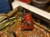
20210219_203932.jpg 20210219_203918.jpg

First pic shows amp board, the little W15-01 board, and the power supply board. Second is more detail of the W15-01. You can see the grey sheath which connects th balance pot to W15-01 "below" the amp board.
 
Neither of my schematics or SMs show a w15-01 pcb. Maybe it is an undocumented addition. Does yours show it?
Can you show the component side?
 
Yes...You may recall that I mentioned it earlier. I think it does show up in the TA version, per an earlier poster.
 
Disregard my results. I was on the wrong balance pot tabs...was reading left channel in both cases. That makes more sense. User error.

Going back to tracing, this time on the correct tabs!! Pots can get confusing, for the simple-minded.
 
I can tell you that when testing, both channels were good on pins 3 (output) of the tone/control board. From there, they go thru filters and loudness, i think, then to balance pot, then to w15-01 and on to the power amp section.
 
Last edited:
That is a notch filter. Lets see if I can figure the frequency . . .
Are they good on the input to the power amp?
 
3Hz ?? Did they have a motorboating problem? Motorboating is usually a power supply problem. Maybe a wrong calculation?

Anyway on with the troubleshooting the real problem . .
 
Last edited:
Ok, just what I expected. Problem is after pin 3 and before the balance pot.

From what I can make of the schematic, the filter switches lie between those two points. Loudness appears to be just ahead of the tone board, if I am reading it correctly...if so, it is excluded, as is the tone/control board itself.

Obviously, the w15-01 is also cleared of wrongdoing!
 
Yes..Good at pin 3. Problem is between there and balance pot. If I am reading the schematic correctly, that leaves the high and low filters, and any components tied directly to them, as the potential culprit.
 
That points at S6 or S7. Deoxit time? Or the 0.2µF caps.
Could be the Low filter switch (S7) contact is open, even in the Off position
 
Back
Top Bottom