• Please note that Audiokarma will be offline briefly for updates early on Monday morning, September 28th.

SX-1010 won't Power On...

I discovered something about the unit. When the DIMMER is ON, the relay engages every time I power up the receiver. But when the dimmer is OFF, no click. When the relay clicks with the dimmer on, in AUX, I tried the headphones, no audio but a slight "POP" in the headphones as soon as the relay engages. Without powering off the unit, I switch to FM (when it's set on a station) from AUX and within a second or two, the relay clicks off again. Those are the up to date symptoms.
 
The dim bulb tester creates a "brownout condition", with reduced voltage. The change in load in bright, and from dim to FM draws just enough power to make the protection circuit think the unit has been turned off..... Apparently it's right on the edge.
 
I guess I didn't make myself clear enough. The dimmer push button ON THE RECEIVER above the FM Mute button. NOT the dim bulb tester. When I push the Dimmer button on the face of the receiver, then turn the receiver off an back on, the relay clicks.

Any suggestions on the STV-3H job? Anything looking dngerous or out of place?
 
I guess I didn't make myself clear enough. The dimmer push button ON THE RECEIVER above the FM Mute button. NOT the dim bulb tester. When I push the Dimmer button on the face of the receiver, then turn the receiver off an back on, the relay clicks.

Any suggestions on the STV-3H job? Anything looking dngerous or out of place?

What we have here is a failure to communicate. I understood you perfectly. What you observed makes perfect sense to me. I just didn't communicate it effectively to you, I was tired from shoveling and some other stuff and wasn't thinking about how to explain it.

The strangeness is caused by the dim bulb tester

The dim bulb tester is causing something that interacts with the dimmer switch and the protection circuit and relay.

Since the dim bulb tester is not glowing brightly, the stv-3h replacement was done correctly.

You can remove the dim bulb tester until we do more internal work on the unit.

Then the stuff you are seeing will go away.

Then we can get down to the nitty gritty.
 
Very well. The symptoms I described were without the DBT, they were observed when the unit was already plugged in directly to the AC outlet. With or without the DBT, it is the dimmer button that decides whether or not the relay will kick in. Might sound nonsense but it is as if the unit is starving for power. Even when the very little power that the internal lights are consuming is reduced, the unit is getting barely enough power to have the relay kick in. Bu then again, that is just a distant possibility, more than that, an amateur opinion. All the same, tomorrow, I will take all the BIAS and idle voltage readings again. I got nothing else to do while waiting for the parts to arrive anyway. Meanwhile, I kept busy and practiced de-soldering and soldering. Getting more and more comfortable with it and the braid makes de-soldering much easier. My only concern is working on the power supply board when it is flipped over. It's not going to be very stable and that will make things difficult.
 
Ah, an easy solution for unstable chassis: I take some 3/4" plywood, and drill countersunk holes that match the mounting holes on the chassis side, essentially making a "side panel" that is much bigger than the end of the unit, to serve as a stable "foot" for the chassis. I also have a "lazy susan" turntable that I set it on, to make turning it easier. With wood at least three times as tall as the unit and the receiver centered on it, it is very stable, it is hard to knock over this way.

(i do almost all of my work with the chassis standing up on end)


WITHOUT the DBT????? :yikes:

That "amateur opinion" is doing pretty good there.

My apologies, i thought we still had the dbt connected. That's the problem with having TWO sx-1010 repair threads going at once, and answering tired...

Is this a multiple voltage or 120v unit?

If there are switched and unswitched power outlets on the back panel, unplug the power cord, turn on the power switch and measure the resistance from each power cord pin to each receptacle opening (both sides) of the three outlets.(that gives six readings for one pin of the power cord and six readings for the other pin of the power cord) There are also two fuses, and one is kind of hidden, it could be damaged. The amount of resistance necessary to do what you have seen should show up on the ohmmeter.


I'm going to bed, I'm getting tired of pulling my foot out of my mouth - I'm gonna get athlete's tongue...........
 
Yes without the DBT. But FIRST I powered up the unit with the DBT. I made sure it went dim as always. THEN I plugged it directly to the outlet. Don't worry, I didn't skip the DBT stage. If the DBT acted strange or noticed something out of the ordinary, I wouldn't have gotten near the wall outlet let alone using it.
 
Yes without the DBT. But FIRST I powered up the unit with the DBT. I made sure it went dim as always. THEN I plugged it directly to the outlet. Don't worry, I didn't skip the DBT stage. If the DBT acted strange or noticed something out of the ordinary, I wouldn't have gotten near the wall outlet let alone using it.

my :yikes: was for the fact that without the tester, it was doing it. :D That was unexpected.
 
Oh. It just brought back bad memories is all, the :yikes: still gives me the creeps. Check post #84 and you'll see what I mean. I thought that your last one was the same :yikes: as the one in #84 is all. :D
 
Mark, the heatsink in the picture heats up within a couple of minutes. It gets REALLY hot although there is no input, output, speakers etc. nothing. Just letting you know. Don't mind me, I just want to make sure you know everything that's going on with the unit, significant or not. I don't want to say "How did I miss that" or for that matter you saying "why did you not tell me about it?!?!?"

P.S: EW, don't worry about the pics, I delete them as I go along. I give them just enough time for Mark to see.

DSC07699.jpg
 
That part does get pretty hot. That regulator gets real toasty. That's normal even if there's no output. I added a few heatsinks on top of it. Here's the pic of mine that had been overhauled.
 

Attachments

  • SX-1010 Regulator.jpg
    SX-1010 Regulator.jpg
    100.9 KB · Views: 52
That part does get pretty hot. That regulator gets real toasty. That's normal even if there's no output. I added a few heatsinks on top of it. Here's the pic of mine that had been overhauled.

WOW, that one got TOASTED!!! I LIKE the remoting of Q8 to the heat sink, and the additional radiating surface attached to the heat sink.
 
Oh. It just brought back bad memories is all, the :yikes: still gives me the creeps. Check post #84 and you'll see what I mean. I thought that your last one was the same :yikes: as the one in #84 is all. :D

Mark, the heatsink in the picture heats up within a couple of minutes. It gets REALLY hot although there is no input, output, speakers etc. nothing. Just letting you know. Don't mind me, I just want to make sure you know everything that's going on with the unit, significant or not. I don't want to say "How did I miss that" or for that matter you saying "why did you not tell me about it?!?!?"

P.S: EW, don't worry about the pics, I delete them as I go along. I give them just enough time for Mark to see.

The easiest to answer first, like EchoWars said, post informative pictures at will, I keep my picture stuff down because I don't want to find out at an inconvienent time that I have exceeded my allotment - as you can imagine I have a LOT of them - BUT a lot pre-date the pioneer database and are schematic fragments. But their removal would leave holes in the threads, especially if they were included in quotes.

I guess I needed a surprised face instead of the yikes... shoulda used the :jawdrop: but I didn't think of it then... my bad...

I will post further on the hot heatsink:

That part does get pretty hot. That regulator gets real toasty. That's normal even if there's no output. I added a few heatsinks on top of it. Here's the pic of mine that had been overhauled.

Yes, that area does get hot, but with this model we can easily test the current drain demands of each power supply, looking for problems. They will be voltage measurements made not to ground, but with one dmm lead on each lead of certain resistors. I'll get a list together later today (to cut down on errors: posting while tired and all that).

but PLEASE remember to do this first, as I requested back on post #326:
markthefixer said:
If there are switched and unswitched power outlets on the back panel, unplug the power cord, turn on the power switch and measure the resistance from each power cord pin to each receptacle opening (both sides) of the three outlets.(that gives six readings for one pin of the power cord and six readings for the other pin of the power cord) There are also two fuses, and one is kind of hidden, it could be damaged. The amount of resistance necessary to do what you have seen should show up on the ohmmeter.
 
The photos that I have on threads in this forum are from Photobucket and they don't show up in attachments in User CP as even being here. If that is the case it would be a good way to go. It's free.
 
What's connected at R18?

Hello, DEK,

What are the purple wires, where C14 (47uF/50V) ought to be, connected to?

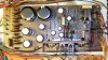
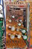
What is the version of your power supply board? Mine is AWR-054-B. It is interesting to notice what could be early vs late production differences between your 1010 and mine. I post the photo of my 1010 power supply board. Note the lack of heat shielding(?) on the R14 and R15 resistors on my unit. Later units apparently also stood these high off the board.
 

Attachments

  • Power Supply Board.jpg
    Power Supply Board.jpg
    110.7 KB · Views: 40
Hello, DEK,

What are the purple wires, where C14 (47uF/50V) ought to be, connected to?

What is the version of your power supply board? Mine is AWR-054-B. It is interesting to notice what could be early vs late production differences between your 1010 and mine. I post the photo of my 1010 power supply board. Note the lack of heat shielding(?) on the R14 and R15 resistors on my unit. Later units apparently also stood these high off the board.

Edit: while this IS D.E.K's thread, the board you are referring to is ccheath's.

It's custom..... but it started out just like yours.

Your board is particularly brown right there, indicating that something got REALLY hot there, what got hot was Q8, which DEK replaced with a higher power transistor that is capable of being mounted on the heatsink, so he took about an inch or so of red and blue and ?? wire and extended the transistor OVER to the heatsink and mounted it on the heatsink. Did a nice job too.

As for those resistors, heat shields, and standing them up, I will discuss them further today later when I really wake up, as they are some of the resistors I want you to measure to check the power supply's loading (and the heat generated). It will be a LONG involved post, that will be highly informative.

By the way, from the colors of the capacitors, they are NOT the originals from the factory, somebody already has worked on this board. It would be really informative to get the markings on the different color capacitors posted, thus we can evaluate what parts were used, their temperature range and maybe their age.
 
Capacitors changed

The previous owner assured me the unit was operational, though it had been stored many years. With old gear, I like to open it up for inspection before powering up. When I saw how toasted the amp board was, I was shocked. Some of the old caps were so bad I did not want to power up before I'd changed them. So I replaced the caps with the best I could get at the time.

The new caps' values are the same capacitance and voltage as spec'd in the SM, and the same values as the original caps I removed. On the toastiest part of the board, I used Panasonic FC 105C caps; the gold and green ones are Nichicon FG and Muse. The Nichicons are only rated 85C, but the old ones looked fine, with no heat stress, so I thought the Nichicons would be fine.
 
The previous owner assured me the unit was operational, though it had been stored many years. With old gear, I like to open it up for inspection before powering up. When I saw how toasted the amp board was, I was shocked. Some of the old caps were so bad I did not want to power up before I'd changed them. So I replaced the caps with the best I could get at the time.

The new caps' values are the same capacitance and voltage as spec'd in the SM, and the same values as the original caps I removed. On the toastiest part of the board, I used Panasonic FC 105C caps; the gold and green ones are Nichicon FG and Muse. The Nichicons are only rated 85C, but the old ones looked fine, with no heat stress, so I thought the Nichicons would be fine.

ok, my memory needed jogging, and I can find NO fault with your reasoning.

edit: LWB, you are crossing threads, and confusing D.E.K... (and me, I guess) the damage is done, so don't edit your posts out. I thought D.E.K could learn something about what a REALLY hot power supply looked like, and I shouldn't have asked the question about your board, no less inserting the statement about power supply loading testing which was directed at D.E.K.
 
Back
Top Bottom