• The move to the new server is done. There are some software and database maintenance updates in process. This has us passing the hat around to help out. We appreciate any donations. Seriously, even a dollar helps. The payment page may be found here - https://www.audiokarma.org/support.html

SX-1250 Restoration

the_burmese

Active Member
Hi folks

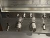
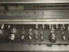
Today I got a chance to get a SX-1250 and I just couldn't pass it up. The unit is in decent shape and working. The main issue is that the switches are pretty banged up. Any suggestion and advice on how to fix them?

My current plan is -
1. Try to remove the faceplate
2. Use one nose plier to hold at the base of the switch arm
3. Re-shape the arm with another nose plier from the tip

Any concerns or guidance on my plan?
Appreciate it so much.

BTW, is there any recommendation on the components that I have got to replace? Thanks again.

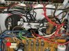
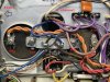
Power switch is in S knot!

0


Tape monitor switches are bent

0
 
Register to hide this ad
Getting full access to the switch is best. Your plan is approved.
Don’t over do it. Getting close to a proper profile is good enough.
if they are really bad:
I’ve never had to do this procedure but I believe it would work with a small butane torch.
Going crazy would require heat which means dissembling the switch and removing the plastic bits. It can be done.
Note:
A side hit of the switch is fairly easy to straighten but the hit from the top where the toggle arm is bent down at the tip is fragile.
Bending the tip vertically requires a life time of tinkering experience - mainly on when to know how much effort it will take and when to say it’s good enough.
 
Pictures do not show.

They will never show when they are Goolge Mail attachments:

https://mail.google.com/mail/u/0?ui...KSUY8&disp=emb&realattid=17684414b424fc2c8641

https://mail.google.com/mail/u/0?ui...LUT6zk&disp=emb&realattid=17684415d4f518a3632

Images will either need to be uploaded as attachment to AK or hosted on a non-Google platform to be accessible by the VBA panel in use. It will only get worse (actually, better) when the Feds finally break up Google into a thousand pieces.
 
As for the switch levers, they are steel, not aluminum. Restraining the lever near the switch body before bending them back to straight is a good idea. I've had good success doing that, but using larger (lineman's) pliers on the end of the lever instead of a second pair of chain nosed pliers. A little heat wouldn't hurt, so long as the switch itself is protected from the heat.
 
The lineman's pliers are a good suggestion.I've used a pair of flat pliers (Craftsman #45087) with good success to do exactly what you are going to do, Did use in conjunction with needle nose close to the switch.
 
Thanks for the great suggestions. (and the seal of approval!) :)

Sorry about the pictures. Hope these works better.

What I am contemplating now is how to remove the faceplate thru these mangled mess .... :idea:


IMG_2792.jpg IMG_2791.jpg
 
Pull the knobs, straighten the levers as best you can to allow removal of the faceplate, and then get serious about "perfecting" their form without worry of damaging the face.

With that kind of damage, it is very fortunate that the potentiometer shafts are not warped as well.
 
Happy new year folks!
Finally got a chance to work on this beast. It is SO heavy that it is quite hard to flip around on the bench!
Straighten up as planned. Still planning to "perfect" them after heating up the tips with soldering iron to soften the metals.

File_000 (2).jpeg

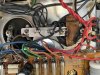
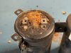
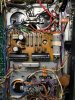
However I noticed something else. One of the decopling caps has some sort of "pad"!!!!!! :confused::confused::confused:
Never seen one like this before. And it looks to me like leaking also.
The unit was operating when I got it. I did notice that the R channel where this leaking? cap is was running a bit warmer than the L side.

Should they be replaced?

File_003.jpeg

File_002.jpeg

File_001 (1).jpeg
 
That is weird.
Kind of a napkin thing.
She going to happy when you replace those big filters.
 
make SURE that when you replace the big capacitors -
BEFORE unhooking either
- MARK DOWN which polarity is where, they ARE OPPOSITE of each other!!!

MARK IT RIGHT ON THE CHASSIS!!!


One supply runs + as hot and - as CHASSIS GROUND

The other supply runs - as hot and + as CHASSIS GROUND!!!


I'll bet that under that brown thing there is something jammed into the capacitor's vent in an attempt to "seal" it.
Check very carefully for bad rectifiers connected to that capacitor - one could be funky in some way and stressing that capacitor.
 
Last edited:
make SURE that when you replace the big capacitors -
BEFORE unhooking either
- MARK DOWN which polarity is where, they ARE OPPOSITE of each other!!!

MARK IT RIGHT ON THE CHASSIS!!!


One supply runs + as hot and - as CHASSIS GROUND

The other supply runs - as hot and + as CHASSIS GROUND!!!


Thanks Mark! I'll definitely follow your advice.
I am preparing mentally and equipment wise to get into this project. First I changed the title since this is gonna be a step by step long restore project.

So far, here is my game plan in steps by steps -

1. Replace filter caps, Rebuild power supply AWR-106-A/AWR-107-0 and protection AWM-091-A boards
2. Rebuild the power amp boards AWH-048-A ( replace caps and recommended transistors from other threads) - plan to spend next week reading up everything I can on AK. here, here and here
3. Rebuild control, flat, filter and equalizer amps

Any suggestion about these steps? I need to break it up since I need to have some sort of check points along the way to make sure I catch any screw ups.

I just got 200W build for my DBT. Hope this is enough for 1250.
Going through the list of lists to get necessary parts from Mouser. And new soldering tip!

It is gonna be a fun 2021, already.
 
Filter caps first, then check operation.
then power supply, recheck operation
then protection INCLUDING C11 and Q11 on each amp board. then recheck operation
then power amps, recheck operation.

The first operations I listed above are all standalone tasks
but the next stuff is too inter related. so
control, flat, filter and equalizer boards should probably be done as a group, to minimize wear and tear (reassembly & disassembly) checking in between.
 
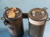
Thanks Mark. Here is the close up pictures of the caps orientation.

Is that how you see as opposite of each other? I think they are matching how the schematics has described.

C1 Neg and C2 Pos to GND
C3 Neg and C4 Pos to GND

I will check which cap is C1 or C3 by tracing the connections
I should have labeled R side and L side. Dont think they are for each channel.

I am getting these from Mouser. Let me know if they are not suitable.

1250 Right.jpg 1250 Left.jpg
 
I was not contradicting the service manual or schematic - but rather warning about unthinking assumptions like -"the negative side of a cap is always grounded... "

your cap choice is fine.

The pictures show (correctly) that on the shorting bar is connected to one cap's positive and the other cap's negative.

It's amazing just how many times after replacing the big can caps that the shorting bar has that wrong.

(usually they are preoccupied with the mechanical details and let the electrical details slip)
 
Hi Mark, I get your point now. Thanks for the confirmation. I am going ahead with BOM list posted by matts as below -

BOM List

647-UKL1H4R7KDDANA | 6
647-UKL1H2R2KDDANA | 12
647-UPW1V4R7MDD | 1
647-UPW1V221MPD6 | 1
647-UPW1H101MPD | 4
647-UKL1H3R3KDDANA | 2
647-UKL1E100KDDANA | 6
80-F612JF224J063A | 2
647-UPW2A471MHD | 4
647-UPW1E101MED | 1
647-UKL1V220KEDANA | 8
647-UKL1C221KPDANA | 4
667-EEU-FM1E471B | 2
667-EEU-FM1E101 | 10
667-EEU-FC1J221 | 2
667-EEU-FM1H101 | 2
667-EEU-FM1V331 | 2
667-EEU-FC1J331 | 2
667-EEU-FM1A221 | 1
647-UPW1C471MPD | 2
647-UPW1V471MPD | 2
647-UPW2A221MHD | 2
647-UPW1H470MED | 2
647-UPW2A470MPD | 2
647-UPW1C470MDD | 3
647-UPW1J220MED | 2
647-UPW1C220MDD | 1
647-TVX1V102MCD | 1
647-TVX2A471MCD | 2
512-KSA992FBU | 15
512-KSC1845FTA | 16
512-KSC2383YTA | 6
512-KSA1013YBU | 3
512-KSC2690AYS | 3
863-MJE15032G | 3
863-MJE15033G | 1
512-KSA1220AYS | 1
512-1N5252B | 2
512-1N4148 | 3
512-1N5234B | 1
534-4636 | 8
534-4672 | 2
653-MY4-02DC24 | 1
653-LY2-DC48 | 1
652-3296P-1-501LF | 2
652-3386H-1-501LF | 2
652-3386H-1-502LF | 2

I also found that he might have missed the 470uF 100V axial lead caps in the Power supply board and 1000uF 25V axial lead cap in the stabilizer board. So I just added them.
Some Panasonic caps in his list are backordered so I changed them to similar types in Nichicon.
Also, I am getting the WIMA caps for 4.7uF, 3.3uF, 2.2uF and 1uF values.

Other than that, I am set to order them from Mouser tomorrow.

My homework while waiting for them is to check all pinout diagrams and orientations of both old and new transistors so I'd put them in the correct order.
I found this to be most challenging part for me - old datasheets are unclear, sometimes contradictory and simply unavailable. Add that on top of errors in the board diagrams and you are bound to get into a real mess real quick. I guess that is what makes experience invaluable.
Will post my cheat sheet to verify and reference here.

Thanks again.
 
Got the delivery from Mouser today!
Marked the terminal polarity on the chassis as advised by MTF. (Oh boy, so relieved that I had when I was putting them back in!)
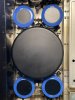
Removed the original caps and here is how they look like -


File_002 (3).jpeg File_003 (1).jpeg

That thing was hardened! There is definitely a leak and a hole. The other one is also bulging visibly.

Now the unit is happy and all shiny!

File_001 (5).jpeg File_000 (6).jpeg

Haven't powered on yet.
Do I need to adjust any bias after replacing them OR I can wait until the very end to do so?
 
Back
Top Bottom