• The move to the new server is done. There are some software and database maintenance updates in process. This has us passing the hat around to help out. We appreciate any donations. Seriously, even a dollar helps. The payment page may be found here - https://www.audiokarma.org/support.html

SX-1250 Restoration

Keep track of which board was originally Left and Right, plug the one that works in the side that is not working and try adjusting it. If it still works the problem is on the other board, if it does not work, the problem is in the chassis. Then try the 'non-working' board in the side that was working. If it adjusts there it confirms the board is good. If it does not work there it confirms the board is bad. If neither works with them swapped the board and the chassis have a problem on the bad side.
 
Swap test show the issue on the R board follows the board. L board on the R side chassis can be adjusted.

Measured collector voltage on Q4 on both sides -

R board -6.88v (neg 6.88v)
L board -1.65v (neg 1.65v)

Something is definitely off on R board.

However, I suspect similar but lesser degree of issue on L side. I could adjust VR2 but it took almost half of the range to get to 40mV. Before I change out the transistors, I could get to 80mV at the same position on both sides. Q4 collector voltage should be -1.8v based on the schematics.

I can try putting the old transistors back in to check. (I saved them just in case.)
 
Last edited:
I am kicking my own rear ... :mad:

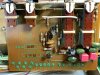
Found cracked solder joint - on emitter of Q7!! Of coz, that would cause mayhem to the bias. :(

Fixed it and now VR2 can be adjusted. Both channels need to be turn up higher than before but I guess new and different transistors have different IV curves.
At least both are now acting the same.

Whewwww .. got scared for an evening. Gotta pay more attention to solder joints ... every time.
Sorry about the false alarm. :oops:

File_000 (13).jpeg
 
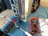
ok, that was THE issue. Bias set around ~80mV for now. The idle current is drawing a little over 1A. (@merlynski I hope I measured it right this time! :biggrin:)
I also measured cold starting inrush. It is almost 14A :eek:. This unit needs to be connected by itself to a breaker in the house panel. :rolleyes:
Any thoughts on these numbers?

After that checking all functions on DBT, and found the FM filter switches kick up the protection - and a slight glow in the DBT. Will address the issue this afternoon. Probably another solder joint issue. :mad:

File_000 (14).jpeg
 
14A does not sound bad, your SX-1250 has a soft-start circuit that limits the in-rush current. It might be over 100A without it, since it has a toroidal transformer. My SX-1050 has two 33,000µF main filter caps to charge, the room lights flicker at cold start, Your SX-1250 has four 22,000µF caps to charge.
Which switch are you referring to as the FM filter?
Clamp meter works better now? :thumbsup:
Remember to turn bias back to minimum before going to full-house mains power.
 
Oh these current draws are from house power. DBT should be much lower.I have 200w DBT so it chokes at about 1.7A.
The ones causing protection are these larger two on the AWM-089 - FM high and low filter functions.


File_001 (8).jpeg
 
That is the Filter Amp board, it affects all signals, not just FM, had me confused there for a bit. The picture straightened me out. Thanks!
Have you replaced Q1 and Q2 on that board?
Measure DC volts on both sides of C6 and C12 with switch off..
 
Last edited:
Found the issue. Q1 was installed in reversed order.
Replaced with fresh ksc1845 and it is now working great.
Newbie carelessness .... :no::no::no::no:

She is now all dressed back up. Expect some eye candy pictures in a bit .... ;)
 
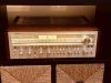
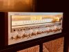
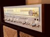
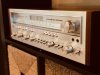
A few eye candy shots .... she is soooooo elegant :)

Nothing fancy - just 4 new warm white LEDs and really really deep cleaning.
She has a couple of scratches on the faceplate and that tape monitor 2 switch might need a new pot. I cant figure out a good way to straighten it.

TIme to burn in those new transistors and electrolytics ... :music:
File_002.jpeg

File_003.jpeg
File_001.jpeg

File_000.jpeg
 
That switch lever can be straightened. However, to do it safely, the faceplate will likely have to come off. Of course, replacing the switch would also involve removing the faceplate, so nothing is lost.

If you get a chance, pull the cap from the switch and post a good photo of the bare lever. I'm thinking is is bent outboard of the double indentation in the lever, which should be the easiest repair.
 
That switch lever can be straightened. However, to do it safely, the faceplate will likely have to come off. Of course, replacing the switch would also involve removing the faceplate, so nothing is lost.

If you get a chance, pull the cap from the switch and post a good photo of the bare lever. I'm thinking is is bent outboard of the double indentation in the lever, which should be the easiest repair.

You nailed it, it is bent at the two indents. Of coz, I'd love to repair it if possible without causing issues.

File_000 (1).jpeg
 
The safest method would be to remove the faceplate, expose the lever, then support the rear (straight) section of the lever and slightly heat the outer end to allow bending it back into position.
 
Alright Gents ....

This is, hopefully, the final post about this project.
Kept it running for an hour and monitored the bias. When input was turn off and volume all the way down, bias settled back to 80mV. Very stable.
Unit gets warm mostly on the stabilizer board. The heat sink for Q2 and Q5 gets pretty warm - it is not burning hot. it is hot to the touch.
The heatsinks are barely warm. Filter caps and the transformer are completely cool to touch.

She sings beautifully. I am not even pushing her yet - volume knob at 10 o'clock only. My SDA-1Cs scream.
Unbelievable almost 50 year old equipment can put out so much quality sound. When people say built like a tank, this is it!
Moving and handling to work on it brought back my carpal tunnel.
A few hiccups here and there but all and all this was such a joy. It was all worth it!
With NEW active and passive components on every board, except the tuner, I hope she will last another 40 more years ( with regular check ups).

If you are die hard Pioneer fan, the search for the power, quality and beauty ENDS with the SX-1250. So does mine.
Also, the fact that I know the history of every solder joint and components, gives it even more personal connection.
I am planning to keep this one - til I kick the bucket. And hope to pass it to my daughter who is also an music aficionado.
Thank you everyone, especially @merlynski and @markthefixer, for guidance and patience. It has been a privilege. :beerchug:

Now, on to the next project ... :p


Bias monitoring and checking as per @merlynski :thumbsup:
File_000 (3).jpeg
 
Last edited:
Hey Burmese, I'm about to acquire a almost mint 1250 that has power supply issues and plan on a total re-cap myself. I did my Sansui 990 with great results so maybe I can tackle this one too. Was it very hard? Any boards very hard to get to? I'll dig up and learn as much as I can before touching the first screw, but would like to know what I'm about to get into before that.LOL!
 
Hey Burmese, I'm about to acquire a almost mint 1250 that has power supply issues and plan on a total re-cap myself. I did my Sansui 990 with great results so maybe I can tackle this one too. Was it very hard? Any boards very hard to get to? I'll dig up and learn as much as I can before touching the first screw, but would like to know what I'm about to get into before that.LOL!

If you have done some restoration before, 1250 isn't hard to work on. In fact, in terms of accessibility, 1250 was a pleasure compared to the cramped SA-9500 I restored before. The only board that is tricky was the filter amp board AWM-089.
Please read up the recommendations and guidance by the pros posted earlier in this thread.

My advice, as a fellow hobbyist, is to take as many pictures as you can at different angles. And take a few more after that. Get a clear pinout comparison between original and new transistors (I felt this is the biggest mine trap I had to wade through in any project.) Get a cheap transistor tester off Amazon and that would save you hours and hours of headache and the magic smoke. And do not rush, get feedback from the experts if and when you start to feel unclear or uncertain. As MTF mentioned, quality takes time!

Enjoy the journey! You will be rewarded wholesomely when you are done. :thumbsup:
 
Back
Top Bottom