• The move to the new server is done. There are some software and database maintenance updates in process. This has us passing the hat around to help out. We appreciate any donations. Seriously, even a dollar helps. The payment page may be found here - https://www.audiokarma.org/support.html

SX-3x00 Receivers - The Mother Lode

To other 3900 owners... hows the tuner section in yours? Mine has, despite my best efforts, remained just 'ok'. My Sansui receivers beat the pants off of it. Other than that, a fine receiver.

I have both a SX-3800 and a 3900. The tuner in the 3800 works better than the 3900. But I suspect the difference is due to age and condition more than anything else. If I could find someone locally I could trust to go thru the tuner section of the 3900 and do an alignment I suspect it would be as good or better than the 3800. However, from all I have read, tuner alignment is a bear of a job best left to epxerts, and I don't know of any such folks locally.
 
I have both a SX-3800 and a 3900. The tuner in the 3800 works better than the 3900. But I suspect the difference is due to age and condition more than anything else. If I could find someone locally I could trust to go thru the tuner section of the 3900 and do an alignment I suspect it would be as good or better than the 3800. However, from all I have read, tuner alignment is a bear of a job best left to epxerts, and I don't know of any such folks locally.

It would be worthwhile to download the SX-3900 Service Manual and see if you are comfortable trying it. If the alignment does not provide a noticeable improvement then your problem may require more work like replacement of capacitor? Which you may have to take in for repair and do the alignment anyway. Also make sure contacts are cleaned.

I recently did a realignment on my SX-939 and improved the performance. I am not an expert and did not know any better. I did not use an FM signal generator or distortion meter as recommended. I just used a pair of rabbit ear antenna as my signal source. The tricky part is following the sequence I would not have known without the manual. There was one adjuster that was marked with solder which I didn't adjust. I decided to see if the other adjustments took without it. For signal strength, adjustment is turning adjusters until you find the sweet spot. As you turn you reach a peak and it will go back down as you pass it. You just turn back until you reach the desired peak setting.

I pulled my SX-3900 out of storage to clean a few weeks ago and it sounded great without an external antenna.
Here's what tunerinfo has to say about the SX-3900 tuner:

Pioneer SX-3900. Our contributor Ryan reports, "The SX-3900 has an analog dial and a digital readout. The dial is just like that on a vintage Pioneer, but a few inches longer. It also has a quartz lock, but Pioneer grew a brain since the TX-9800, and you can disable it on the front panel. The tuner has a 4-gang analog cap, and a single gang varactor for the oscillator, so the thing has a 5-gang tuner stuffed inside it. Nice. Stereo sensitivity is great at 36 dBf. The S/N ratio is 78 dB in stereo, which is pretty impressive in any vintage beast from 1980 or so, especially in a receiver. The only pitfall is the single IF bandwidth, which uses 3 GDT filters and two HA1201 IF amps. Even so, distortion is only .2% at 6 kHz and you get 80 dB alternate channel selectivity to go with it. Anyhow, the spurious responce is 100dB, which is pretty decent. The rest of the package is rounded out by a nice toroidal transformer, two 15000 uF caps, and a good 120 WPC output. THD is .005%, but the damping factor is surprisingly only 60 from 20 to 20, which suggests that there might not be all that much negative feedback to pull off the low THD, but good design instead. A 115 dB A-weighted hum and noise suggest pretty good design. Pioneer also developed some updated tuner ICs which are in this thing instead of the old PA1002, etc. which were in their older tuners and receivers. As a transition product (from analog to digital), this thing was probably at the leading edge of analog Pioneer receiver technology."

Translation .. It should sound better than ok.
 
Old thread . New find. An sx 3600 in the thrift today for 25.00. I go into the back and told the gal the loudness switch cracked ( it did, slightly). and could you do something? Sure, 12.00. That did it. Perfect unit, this stuff is like crack when you see it sitting there.
 
This is a pretty old thread I know but can someone put up a link or the correct specs for the indicator button lamps, i.e. channel indicators and source indicators. I have a couple out and would like to replace them. Just want to make sure I get the right diameter more than anything. Thank you.
 
If anyone has a source for the red and green lights behind the selector and speaker switches, I'm all ears....need a few for my SX-3900
red and green lights are actually just ordinary lights with red and green lenses on the front of the unit
I have just ordered a set of replacement lamps for my SX 3700 check joesoldaudio on eBay
 
This is a pretty old thread I know but can someone put up a link or the correct specs for the indicator button lamps, i.e. channel indicators and source indicators. I have a couple out and would like to replace them. Just want to make sure I get the right diameter more than anything. Thank you.
check joesoldaudio on ebay
 
Just found a 3700 on Craigslist for $60. Great shape, works great, couple indicator lights out, sounds great. Not as much separation or clarity as my ELITE, but much better for inferior recordings or with sibilance.

cxOLlQZ.jpg
f3ocmRK.jpg
 
I'm reviving this topic with a way to change the speaker selector bulbs on the SX-3700... without having to mess with the dial cord (which I simply dislike doing).

After buying a replacement bulb:
1) Remove the wood bonnet by taking out the four screws.
2) Take out the two black screws holding in the clear acrylic lamp board.
3) Gently slide the lamp board back until it's free.
4) Looking down onto the left front side of the unit, unscrew the two silver screws holding the florescent board in place.
5) GENTLY, move the board back and BENEATH the dial cord. It will only go back a few inches, but that's all you need.
6) With the florescent board resting, look beneath it and see the slots for the a/b speaker bulb wires (A speakers are two white wires, B speakers are two black wires).
7) Remove the faulty bulb from its lamp socket.
8) I found I could work easier with more lamp wire exposed. Using a long needle-nose pliers, untangle the white wires from the black. You should get some slack to work with.
9) Clip the bulb wires as close to the bulb. Strip the wire enough for the reconnection. I needed about four millimeters. You may need less or more.
10) Solder or Western Union splice your wires to the bulb wires. There is no negative or positive. Either will do. Once done, push the bulb into its lamp socket.
11) Use electric tape or whatever you like to secure your work. Make sure you don't have any exposed wire, or any bare wire touching anything.
12) Gently place the fluorescent board back in place, making sure to go under the dial cord.
13) Secure the board with the two silver screws.
14) Check your work. Make sure the lamp comes on.
15) Slide the acrylic lamp bulb board back in place, making sure to line up the screw holes.
16) Reinstall the two black screws to hold it back in place.
17) Place the wood bonnet in place and secure it with the four screw.
18) Enjoy...!

This is pretty much what a previous poster advised, but I was scared because I didn't want to screw up by putting any slack in my dial cord. That's a tough problem to fix. Using my way, you just have to delicate and gentle with the fluorescent board. The faster you are at soldering, the quicker this project goes. I could see it being a half-hour job.
 
Last edited:
Anyone know where to get a set of speaker outputs for a 3700? Looked on Epay, Oaktree, AW in Toronto and they used to have some but sold them.
 
Anyone know where to get a set of speaker outputs for a 3700? Looked on Epay, Oaktree, AW in Toronto and they used to have some but sold them.
What so you mean by “speaker outputs”. Do you mean speaker terminals or output transistors? I have a parts 3700.
 
I recently decided I must have one of these Flouroscan 3x00's, I just LOVE the look, so I did some research.
I landed on the SX-3700 being "ideal" for my needs, doing my research I found that:

-The SX-3600 and lower are Korean?
-SX-3700 and up are Japan made. Yes, I'm a snob like that.
-The SX-3600 and possibly 3500 have plastic switches that commonly break, I wonder if it's a design issue or materials quality issue (not made in Japan)
-The faux wood execution on SX-3700 and up generally looks better and many of the 3600 and lower I found were bubbling...
-The 3800/3900 use NSA topology....according to the trusted experts here, kind of a tricky setup to fix, and I'm very comfortable with repairing the more basic circuits in the gear I already own, didn't want the challenge....

So, I recently bought a SX-3700. I focused on good case condition and apparently still functioning well. I will immediately refurbish it and replace all of the lamps, probably going with incans on the dial just to maintain that contrast of "old school vs new school" that makes these look so good.

How do the VF displays on these hold up over time? I have some VF clocks from the early 80's and they seem to be holding up pretty well, no major dimming so far. I presume they are "on" far more than the displays of these receivers.....
 
Can't answer your tech problems but will agree that the fluroscans are some of the most elegant looking receivers. I have a SX-3900. I also had to have one once I saw one. Sounds great but hope I don't have issues with it as I've read here that they are a bitch to service.
 
Growing up, when these 1st appeared I loved the futuristic look and had to have one, one day. Now? I'll take a sx-80 series any day over one of these. Strange how my own opinions change.
 
New here, as a lover of the silverface era, I found an SX-3700 (probably paid too much for it ) it's in excellent condition veneer sides almost mint - both speaker selector bulbs, & AM & FM selector bulbs out - I found this thread in my search for info regarding replacement of said bulbs
I may attempt to replace them, I may not - If anyone on here knows of a reputable tech who repairs (restores) good 'ol electronics around central Indiana, please post some contact info!
 
I'm reviving this topic with a way to change the speaker selector bulbs on the SX-3700... without having to mess with the dial cord (which I simply dislike doing).

After buying a replacement bulb:
1) Remove the wood bonnet by taking out the four screws.
2) Take out the two black screws holding in the clear acrylic lamp board.
3) Gently slide the lamp board back until it's free.
4) Looking down onto the left front side of the unit, unscrew the two silver screws holding the florescent board in place.
5) GENTLY, move the board back and BENEATH the dial cord. It will only go back a few inches, but that's all you need.
6) With the florescent board resting, look beneath it and see the slots for the a/b speaker bulb wires (A speakers are two white wires, B speakers are two black wires).
7) Remove the faulty bulb from its lamp socket.
8) I found I could work easier with more lamp wire exposed. Using a long needle-nose pliers, untangle the white wires from the black. You should get some slack to work with.
9) Clip the bulb wires as close to the bulb. Strip the wire enough for the reconnection. I needed about four millimeters. You may need less or more.
10) Solder or Western Union splice your wires to the bulb wires. There is no negative or positive. Either will do. Once done, push the bulb into its lamp socket.
11) Use electric tape or whatever you like to secure your work. Make sure you don't have any exposed wire, or any bare wire touching anything.
12) Gently place the fluorescent board back in place, making sure to go under the dial cord.
13) Secure the board with the two silver screws.
14) Check your work. Make sure the lamp comes on.
15) Slide the acrylic lamp bulb board back in place, making sure to line up the screw holes.
16) Reinstall the two black screws to hold it back in place.
17) Place the wood bonnet in place and secure it with the four screw.
18) Enjoy...!

This is pretty much what a previous poster advised, but I was scared because I didn't want to screw up by putting any slack in my dial cord. That's a tough problem to fix. Using my way, you just have to delicate and gentle with the fluorescent board. The faster you are at soldering, the quicker this project goes. I could see it being a half-hour job.
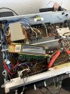
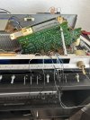
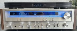
Thank you so much for this guide, it helped me tremendously! Before and After pictures and some of the boards moved out of the way for context for the next person attempting this.

Pioneer wout lights.jpg

Pioneer5.jpg

Pioneer4.jpg
Pioneer With Lights.jpg
 
Last edited:
Back
Top Bottom