

You are using an out of date browser. It may not display this or other websites correctly.
You should upgrade or use an alternative browser.
You should upgrade or use an alternative browser.
Register to hide this ad

Your wife attacked it with an ice pick?
She ran off with it?
She decided she liked it????
She ran off with it?
She decided she liked it????


What I am about to say pales into insignificance after all that funny stuff....
Anyway, so I have this C-2102 as a partner to the B-2102 which I have done a basic 'freshen up' on so far.
I have used the C-2102 and it sounds OK, - obviously some 'class' showing, and it sounds nice, no more than that, I am a little underwhelmed by the Parametric Equaliser about which great things have been said.
The C-2102 has been 'interfered with' by it's previous owner 'Mr Idiot' who I will refer to as just 'Idiot' - so I get it on the bench and I want to have a look at the PSU closely with the scope to see what the regulation and noise are like. The 'glue' hasn't been removed, and new very ordinary electrolytics have been put in on top of crusty mounds of the stuff, and several resistors are drowning in it. The output voltages seem ok EXCEPT the main regulator, which should be +/- 30V but is actually outputting +/- 24V My first thought (bearing in mind I have seen idiots 'work' in the B-2102) is that the zeners are the wrong voltage.
The 3 PCB heatsinks are very hot, especially the middle one with Q1 on it, (some deja-vu here if you read the B-2102 write up ) - I check the zeners - they are 11V, 1W types and should be 13V 500mW
  - I can't imagine what possessed idiot to do that. Anyway I change them for 13V 500mW and we get +30V, but wait... where is the -30V ??? I get zero output, nothing, nada... 40+ volts going in but nothing coming out. So, I remove a couple of transistors and test, and they check out ok, a bit more searching.... whats this? a 12K resistor (R11) reading 'open circuit' - the resistor is covered in glue, and has blue green 'fuzz' at each end. I remove it and it looks physically fine but is OC. new resistor fitted and now I have +/- 30V - Hurrah !!!
Those hot heatsinks, now it is clear, 45V input, 24V output = hot regulator, 45V input, 30V output = cooler regulators. I think Idiot must have noticed how hot the heatsinks were, and removed the series 4.7Ω dropper resistors and untidily fitted 2 parallel pairs of 12Ω resistors (for 6Ω) to increase the volt drop to the input of the +/-30V regulators in an attempt to help this situation, a fat lot of good that did.
There are 4 stake terminals in the board to carry the +/- 30V to the main PCB, did Idiot unsolder the stakes? - nope - he hacked the (blue and red) wires off, and to reconnect soldered them to the bottom of the PCB !!! - Missing are the nearby ground stakes - I'll be putting this right after I clean and rebuild this PSU board to refresh the capacitors and other glue damaged components.
Thankfully it looks like 'idiot' chickened out and didn't get to the main board, as everything looks original there and elsewhere, more on this when I get to it.
Oh, and I did a listening test on the C-2102 with the now correct +/- 30V - much much better - a lot more of that 'class' peeping out now.
In case you are wondering, 'Idiot' isn't an AK member, certainly not an active one.
Anyway, so I have this C-2102 as a partner to the B-2102 which I have done a basic 'freshen up' on so far.
I have used the C-2102 and it sounds OK, - obviously some 'class' showing, and it sounds nice, no more than that, I am a little underwhelmed by the Parametric Equaliser about which great things have been said.
The C-2102 has been 'interfered with' by it's previous owner 'Mr Idiot' who I will refer to as just 'Idiot' - so I get it on the bench and I want to have a look at the PSU closely with the scope to see what the regulation and noise are like. The 'glue' hasn't been removed, and new very ordinary electrolytics have been put in on top of crusty mounds of the stuff, and several resistors are drowning in it. The output voltages seem ok EXCEPT the main regulator, which should be +/- 30V but is actually outputting +/- 24V My first thought (bearing in mind I have seen idiots 'work' in the B-2102) is that the zeners are the wrong voltage.
The 3 PCB heatsinks are very hot, especially the middle one with Q1 on it, (some deja-vu here if you read the B-2102 write up
) - I check the zeners - they are 11V, 1W types and should be 13V 500mW - I can't imagine what possessed idiot to do that. Anyway I change them for 13V 500mW and we get +30V, but wait... where is the -30V ??? I get zero output, nothing, nada... 40+ volts going in but nothing coming out. So, I remove a couple of transistors and test, and they check out ok, a bit more searching.... whats this? a 12K resistor (R11) reading 'open circuit' - the resistor is covered in glue, and has blue green 'fuzz' at each end. I remove it and it looks physically fine but is OC. new resistor fitted and now I have +/- 30V - Hurrah !!!Those hot heatsinks, now it is clear, 45V input, 24V output = hot regulator, 45V input, 30V output = cooler regulators. I think Idiot must have noticed how hot the heatsinks were, and removed the series 4.7Ω dropper resistors and untidily fitted 2 parallel pairs of 12Ω resistors (for 6Ω) to increase the volt drop to the input of the +/-30V regulators in an attempt to help this situation, a fat lot of good that did.
There are 4 stake terminals in the board to carry the +/- 30V to the main PCB, did Idiot unsolder the stakes? - nope - he hacked the (blue and red) wires off, and to reconnect soldered them to the bottom of the PCB !!! - Missing are the nearby ground stakes - I'll be putting this right after I clean and rebuild this PSU board to refresh the capacitors and other glue damaged components.
Thankfully it looks like 'idiot' chickened out and didn't get to the main board, as everything looks original there and elsewhere, more on this when I get to it.
Oh, and I did a listening test on the C-2102 with the now correct +/- 30V - much much better - a lot more of that 'class' peeping out now.
In case you are wondering, 'Idiot' isn't an AK member, certainly not an active one.
Last edited:

I've been mulling over this whole 'hack' thing for a while now. Given how many of these gems are turning up on our benches these days I am starting to wonder how many repair facilities in the 80's, back when there were repair shops, put expediency ahead of correctness and grabbed whatever they had handy to make a unit usable rather than source correct original parts. I do not recall that many hobbyists working on gear back then at home. Case in point, restoring a SX-1010 at the moment that had been in once in its life for repair according to original owner that although at first look appeared original had had one of the driver boards cut out and replaced with a different series (d) board soldered in rather than a repair of the original component. Also, the affected channel had GE and ECG outputs installed, incorrect transistors for pre-drivers etc. Functional yes, correct as we expect, no. To John's original post, it takes a ton of diagnostic time to uncover these hidden repairs, often resorting to component by component verification, although I must admit taking a magnifying glass to the solder side of the board will often lead one quickly to much of the tell tale signs of previous repair since old flux, solder blobs and scrape marks along with lifted pads etc will give that work away. Well done once again John 
-Lee
-Lee

ghazzer
Senior Member
Thanks for the superb narrative John. Hard to tell if you were laughing, steaming, or both, but trying to get a picture of that in my mind has been very entertaining - Thanks.
Other than some tweaks to my 5000- back in the 70s the only other receiver I have worked on has been this G-6700 (and it may be my last!). I started a letter to tape in an envelope to the bottom plate, telling future owners what I had done to 'repair' the unit. At this point there are soooo many pages that the folded stack may be thicker than the rubber feet (haha).
Anyway, I will definitely condense my missive and attach it with gorilla tape.
Side note: This will be my 1,945th post on AK - the same as the year of my birth . . .
Cheers - - -
Other than some tweaks to my 5000- back in the 70s the only other receiver I have worked on has been this G-6700 (and it may be my last!). I started a letter to tape in an envelope to the bottom plate, telling future owners what I had done to 'repair' the unit. At this point there are soooo many pages that the folded stack may be thicker than the rubber feet (haha).
Anyway, I will definitely condense my missive and attach it with gorilla tape.
Side note: This will be my 1,945th post on AK - the same as the year of my birth . . .
Cheers - - -
What I have seen written on AK about some equipment worked on by people who are ignorant or simply don't care, makes the above seem quite trivial.
Just one more thing, idiot had clearly noticed the glue corrosion because several of the jumper wires on the PCB had a blue-green bloom of corrosion around them. Anyone with half a brain would remove clean and replace? - not idiot, he just put another jumper on the underside of the PCB in parallel with the corroded one - just to make sure - really amazing.
Just one more thing, idiot had clearly noticed the glue corrosion because several of the jumper wires on the PCB had a blue-green bloom of corrosion around them. Anyone with half a brain would remove clean and replace? - not idiot, he just put another jumper on the underside of the PCB in parallel with the corroded one - just to make sure
- really amazing.savatage1973
Addicted Member
This is an excellent example of why I'd rather buy an unserviced/unmolested/DOA piece rather than something listed as "recently serviced"--unless there are detailed receipts/invoices from a recognized tech/shop. There are far too many "idiots" and amateurs out there that do just enough damage to get something up and running for sale. If I buy something "cheap" in non-working order or with "issues", I know what I'm up against and can anticipate the project ahead. If I pay a "premium" price for something that is allegedly serviced or refurbed, I want full documentation and perhaps even a short warranty. The words "just fixed" or "just repaired" send chills down my spine when I read them in a listing.
The PSU fully redone now, all voltages checked and stable, heatsinks are hot but OK in my opinion.
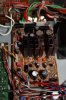
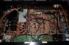
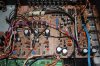
Here are a couple of pictures, slightly different views, nothing much different to see, but in the 'before' picture you can see the hacked off blue and red wires (to the right) and the missing ground stake(s) in between them. (pictures from left to right, before - after).
Here are a couple of pictures, slightly different views, nothing much different to see, but in the 'before' picture you can see the hacked off blue and red wires (to the right) and the missing ground stake(s) in between them. (pictures from left to right, before - after).
Attachments

Last edited:
After ---------------------------------------------------------Before
Thankfully it looks like 'idiot' chickened out and didn't get to the main board, as everything looks original there and elsewhere, more on this when I get to it.
Well, a few days ago I was having a close look at the main board, and found the tell-tale signs of some 'action' around some of the transistors on the main board F-4606. The solder joints were not original, what's this? - more transistor changing! The previous owner seems to have this 'thing' about 2SA992's and 2SC1845's - he likes changing them to 2SA970's and 2SC2240's - so I find 10 transistors like this in the 'EQ' section (=phono amp). So I go through my stock of KSA992's and KSA1845's (the correct transistors for these positions) and find a few pairs of each with very similar hfe, I replace the transistors Q1-Q5 which have been changed. I have now re-capped the 'Flat Amp' section and four of the power line filter capacitors for the EQ section (still on the F-4606 board), I have a few more signal path and a power filter capacitors that remain to be done in the EQ section to finish it off. I have some nice Nichicon Muse bipolars to replace the the signal path 'made-up' bipolar pairs of capacitors.
The new KSA992's hfe were measuring roughly 350-430, and the new KSC1845's from about 380-460 approximately. Guess what the hfe of the removed transistors is/was? - all around 200-250 but with one rogue 2SC2240 measuring an amazing 639 !!! (the 2SA970's were marked 'GR' which should have yielded better hfe - but I am guessing they were fairly recent purchase and probably counterfeit).
I decided to give it a listen, brilliant !!! more & more improvement, imaging & soundstage benefitting greatly. Listening to DSOTM on vinyl now (what else?
 ).
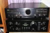
).Two trimmers are yet to be replaced in this picture, they have now been changed.
Thanks for reading.
Attachments
Last edited:

Similar threads


- Replies
- 18
- Views
- 2K
