Follow along with the video below to see how to install our site as a web app on your home screen.
Note: This feature may not be available in some browsers.
The move to the new server is done. There are some software and database maintenance updates in process. This has us passing the hat around to help out. We appreciate any donations. Seriously, even a dollar helps. The payment page may be found here - https://www.audiokarma.org/support.html
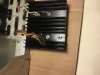
Is this thermal paste? It is just a thin film between the brown metal piece and heat sink. The brown metal does has 2 brown wire connected to it. Why it is needed here, It seems not that much of heat to dissipate? Any idea? Thanks.
Sorry, I thought this is pretty common. Learning here.
It is an integral amp JVC VN 900. Going to temporarily remove it for access to replace the output transistors. And wondering should I replace this film with new thermal paste or not? Any input would be appreciated.
Is this thermal paste? It is just a thin film between the brown metal piece and heat sink. The brown metal does has 2 brown wire connected to it. Why it is needed here,
Is this thermal paste? It is just a thin film between the brown metal piece and heat sink.
Yes.....The brown metal is likely either some kind of temperature sensor for thermal tracking the bias. Its needed to prevent thermal run away.
Looks like it has been arcing or shorted to the heatsink judging by the burnt / missing anodizing around the mounting screw. Likely missing a mica insulator.
Looking at the schematic it looks like it's some strange version of a thermistor used for bias tracking as Avionic said. Not sure if it needs an insulator but I'd definitely put thermal compound on it. test for continuity between the leads and the part that contacts the heatsink.
study the schematic and Google a bit, remember I have very limited knowledge in this. I was guessing it is the "TH" thing on schematic and confirmed by googling more. Still don't know how it works though.
And the regular nonconductive thermal paste used in the transistor is OK to use here, I assume. Thanks.
study the schematic and Google a bit, remember I have very limited knowledge in this. I was guessing it is the "TH" thing on schematic and confirmed by googling more. Still don't know how it works though.
And the regular nonconductive thermal paste used in the transistor is OK to use here, I assume. Thanks.
Yep that's the thermistor. A thermistor is pretty much a resistor that changes resistance in relation to heat so so for example at 20°c it could be at 100 ohms and at 80°c it could be at 1,000 ohms. They all have varying specs. Yeah same thermal paste used on the outputs will work and remember. The bigger the glob the better the job.
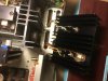
This is how is was mounted and they seems all electronically connected together. If this is the case, I shouldn't be worrying about the nonconductive part, isn't it? even with the old thermal film, I don't think they are providing complete isolation from the heat sink electrically.
This is how is was mounted and they seems all electronically connected together. If this is the case, I shouldn't be worrying about the nonconductive part, isn't it? even with the old thermal film, I don't think they are providing complete isolation from the heat sink electrically.
Depends, is the case of the thermistor electrically conductive? set your meter to continuity test mode (where it beeps if you hold the probes together) and measure from the solder on the thermistor to the thermistors body. Do it for both solder joints, if it beeps then yes it probably needs a insulator, if not then it's fine. Did it have a insulator like the output transistors to begin with?
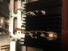
No, when I pulled it up as shown in the pic, there is only this thin layer of grease. No insulator. Does this still imply any thermal paste could be used for my case?
No, when I pulled it up as shown in the pic, there is only this thin layer of grease. No insulator. Does this still imply any thermal paste could be used for my case?
If it didn't have one before and it was working I'd assume it's okay that thin layer of grease is some kind of old thermal grease but ye any will work I use computer thermal compound but most techs use the white silicon thermal grease
Still how does this thermistor work? Seems like it is a mechanical device? when it heats up, the plate deforms and somehow the resistance increases? Or it is something to do with the bronze pine attached to the screw and this brown plate?
Still how does this thermistor work? Seems like it is a mechanical device? when it heats up, the plate deforms and somehow the resistance increases? Or it is something to do with the bronze pine attached to the screw and this brown plate?
Not a mechanical device, it changes it's electrical properties with heat. You'll have PTC or NTC thermisters which will go up or down in resistance depending on temperature. https://en.wikipedia.org/wiki/Thermistor
Replace the output transistors, new mica and thermal paste, also thermal paste under the thermistor. The film is the original thermal compound can be seen under the other channel’s transistors. Put eve thing back, test it and seems working fine. Thanks for everyone’s input and help.