• The move to the new server is done. There are some software and database maintenance updates in process. This has us passing the hat around to help out. We appreciate any donations. Seriously, even a dollar helps. The payment page may be found here - https://www.audiokarma.org/support.html

Tube Power Supplies a Different Approach!

I like the 37 too, and it's a good looking tube as well. They are getting pricey though. All of the ones I have are Mullards, did anyone else make them?

Jay I really don't know, I don't think so.

Its to bad Cary used so many, I would imagine they contributed to the rise in cost of the 37. I think some of its sweet sound is from near 3 amp filament. I am finding that there are a lot of reasons that supplies sound different from one another. I did use Duncan's PSUDII to tune the 45 amplifier's supply noise spec. Pretty amazing how the basic design can go from a few mV to tens and tens of mV. But really layout can contribute more and often does. I think often people are to honed in on zero noise instead of taking advantage of an output transformers step down ratio.

But I'll tell you as reported from John the builder of the BOS45 amplifier as he has named it, the 6D22S Tube Bridge Rectifiers are sounding very fine indeed and really looks to be the way I'll be going and I found some damper diodes with even more impressive specs that don't use top caps for those who want to stay away from them.

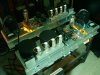
bos45botbench.jpg


SET12
 
Chokes to use

In the interest of continuing conversation here, in the correct thread...

An idea I've come to like more recently is that you can go with Dans brute force approach here and definitely get the benefits of minimizing DCR in the supply...but another option exists for the minimalists out there.

With the 193R chokes listed above.... about .3 henry and 3.5 ohms DCR... you don't get much isolation between stages. Dan add's diodes there to fix that...in absence of that I've found that the $10 Triad C40X .32henry 10 ohm is a bit easier to work with when using much less C in the supply.

The Hammond 159ZA is also .3 henry and 6 ohms... I found I liked it a bit better than the 193R...however it is open bracket....and only $27 each.

Hammond has a few more good offerings... a .6H at 11 ohms looks real good to me... and you can get 1.5H from them @ 25 or so ohms DCR.

Edcor is the current champ of budget LOW DCR GOOD chokes...2 henries, 21 ohms DCR and $31.

I think when you get a bit more resistance in the choke, around 10 ohms you get some advantages...Setup with 2 or 3 stages with .5 henry chokes you can use small caps and have another type of "low DCR" supply...Smaller caps, around 50uf maybe even upwards of 100uf can be film caps...and you can skip the slow warmup and bulk electrolytic all together.

When you get to the more "moderate DCR approach" you can use PSUD to tune the values in the order that works best...and end up with a supply that can do 80% or better of what the above does, with far less components.

Just another crazy out in left field approach to the same end. If you size the PT large enough the big bulk of capacitance isn't as necessary for some people.

Maybe a mod could change my tag to "low dcr troll"? :)

I've actually tested the Hammond 193R vs the Triad C40x vs the Hammond 159ZA.

With 100ma current draw in a KT120 SE amplifier I found the Hammond 193R buzzed as a "quasi choke input". The Triad C40x also buzzed. The Hammond 159ZA did not buzz.

In the second position in an LCLC supply the Triad C40x filtered the most, followed by the 159ZA and in last was the 193r. This was measuring noise, ac on the output transformer at idle with speakers connected.

Thanks Sean,

I certainly need to investigate that option more thoroughly.

FWIW I have had no issues with the Hammond 193R. The 159ZA .3H 1 Amp 6 ohm's 500VDC vs the 193R 1 Amp 3.5 Ohm's 1000VDC. I would expect more trouble from the AZ, but read below the comments from John S.

But whats interesting is my current supplies in my 811-10 approach nearly the same DCR's your working with in total all ready but perhaps a bit more. While within my own supply after the transformer and rectifiers is a lower DCR yet 5 ohm's along with the massive reserves and of course diode decoupled.

I can't imagine bringing this down to a 7 ohm secondary :scratch2: and 800VA capacity after looking at what is available. This would bring me down to a mere 12 ohm's total. And after I get done with the rectifiers well, it will be a monster.

Maybe a mod could change my tag to "low dcr troll"? :)


I'd be happy to give it a shot :D

80% :-) BTW, it may be very well that its the last 15-20% of the throttle that lay's you in the back of the seat sort to speak :yes:

The only way for you to tell is to get here :smoke:


"quasi choke input"

"Quasi" choke input supply is one with a low value input capacitor and the input capacitor has an extremely high slew rate. The low value and high slew rate combine to make the capacitor virtually invisible to the audio signal while substantially reducing the hum in the power supply. The choke input capacitors are 1 MFD with a slew rate of more than 500 V/uS.


Boy did I see this thing go to work in Duncans, But what I see is tuning can be all over the place for the amount of noise ended up especially in a design like your working with. But I'm all for what ever works for you!

FWIW I have had no issues with buzzing with the Hammonds but of course this can very from supply to supply read on below!


Further information from designers that I feel are very cutting edge designers

A couple of good points about using chokes especially ones where one may think are or are not correct!


Posted by John Swenson (A ) on July 22, 2006 at 21:53:32
In Reply to: Operating Hammond choke near V limit posted by fred76 on July 22, 2006 at 15:22:45:


The DC voltage for the choke is NOT necessarily the same as the B+, the choke is in series with the supply, thus its the voltage DROP across the choke that matters. You can have a 600V B+ with only 10V across the choke.

The big issue is not the DC voltage but the AC voltage across the choke, that is what determines whether its going to buzz or not or saturate. Unfortunately thats going to vary all over the place from design to design, its almost impossible to determine it from just the B+ voltage.

I think Hammonds spec is based on building a C input supply with a certain range of caps done in a "standard" design, in which case the AC voltage will be in range if you keep the B+ voltage below the rated value. I don't think its an actual voltage rating for the insulation.

If you start using choke input or using cap values out of the "standard" range (whatever that is) you can go over the AC rating even though you are within the DC rating.

For example in a amp I've been playing with I had two different arrangements of the same caps and chokes (Hammond), in one configuration there was 140VAC (RMS) across the first choke, it buzzed like mad. The second configuration had 16VAC (RMS) across the same choke, it worked fine in that case. Both had the same transformer and output voltage.

So unfortunately there is no hard and fast rule. "It depends" is the best we can do without a lot more detail about the supply.

John S.


Posted by John Swenson (A ) on September 22, 2006 at 15:40:22
In Reply to: Exceed maximum voltage rating on choke? posted by jdm6457 on September 21, 2006 at 11:59:17:


Is this by any chance a Hammond choke? If it is that 400V DC rating has nothing to do with the voltage rating between the winding and the core (which if I remember correctly is much higher) its their attempt at not publishing the AC rating of the choke.

What it means is that for an "average" cap input supply producing 400V DC B+ the choke can handle the AC voltage developed across the choke. It has nothing to due with the insulation and everything to do with the magnetic properties of the choke. The actual AC voltage across the choke (remember thats NOT the AC voltage coming out of the transformer, or the voltage at the choke pin to ground, but the voltage from one end of the choke to the other) can vary quite a bit depending on the cap values used, etc. Before the advent of simulations it was hard to compute the value without actually building the supply, so Hammond chose not to give the AC spec.

I think Hammond had gotten burned too many times by people not understanding what the AC voltage across the choke means, that they just sidestepped it all together and said if you use a cap input filter and keep B+ under 400V you should wind up within the AC range of the choke.

In your application the above means that you should be fine with this choke. I've used one of their "400V" chokes in a 700V supply with no problems what so ever, but I made sure that the AC voltage across the choke was not that large. If you use it in a situation with large AC voltage across the choke (such as in a choke input filter) then they get hot and buzz, not so good.

John S.


Cheers

SET12
 
Last edited:
I would assume that Hammond uses the same standard 1500v varnish insulation on all of their chokes, so the voltage rating has nothing to do with the insulating of the wire. As far as actual voltage across a component, the same logic can be applied to coupling capacitors. With a typical 450v B+ you may read 185 across the cap. They put the higher rated caps in because of the potential, but if you minimize or eliminate the causes for an over volt situation, you can use those those 200v rated Hyrels that have been sitting around for 60 years.:yes: I'm definitely in the push it if need be camp for my gear, but way more conservative on other folk's stuff.
 
Hello,

Since I have been mentioned in this thread numerous times, I thought I would add a thing or two that may help some readers and DIYers.

First of all, I have been playing with DCRs of Power Transformers and chokes in audio equipment continuously for about 35 years, and "playing hard". I am still at it. ( This week I added two 250 VA Signal Power Transformers to my CD Player, that is over 10 Amperes, each trannie !! )

I TOTALLY agree with SET12 about reducing 100 Ohms of added series resistance to the Finals of a tube amp. The people who are saying "its raising voltages" frankly are whistling in the dark !!

Also, you can't judge anything very well at all with a Varaic on the primary of a power transformer, it ruins dynamics.

Also, there is NO Free Lunch. Use of an ANTEC toroid may give you "cheap" Low DCR, but a Toroid is a wide band device, and as such, it very ably couples line noise to the audio circuit. A conventional E-I core will be much better in that regard as it is not as wide band.!!

Years ago, after my original audio mentor died in 1988 ( Bob Fulton ), I had two mutual Audio Friends mentor me additionally, Dennis Fraker and Dr. Charles Halijak. Charlie put the first mammal out into space for the USA, a monkey, pre-human flight. He was the EE who pulled that off. And Dennis Fraker now builds the world's BEST commercial SET amps, a DC 2A3 amp monoblock. His amp design, MLTL speakers, and reviews can be accessed over at serioustereo.com. and heard at RMAF Denver this November. Or, look here:

http://parttimeaudiophile.com/2011/...us-stereo-command-performance-berkeley-audio/

Unfortunately, we have lost Dr. Halijak, he died many years ago. He was a kind audiophile who would NOT let any EE pass his courses until they designed and built a TUBE audio amplifier, for all in the class to hear and design-evaluate!! Some Professor .

For all of you who have read this nine page thread, I will share with you his " baptismal " of mine into Low DCR. Low DCR I had known from extensive parts-subbing over the decades. Dr. Halijak gave me the theory.

Here it is, read his Letter to me, on the " Figure of Merit on a Power Supply ". Today, I call 20 Ohms and less "High Fidelity" and 10 Ohms and less " Ultra High Fidelity" Thats for Power Transformer AND choke winding DCRs. Here we go, fellow audio friends :

http://db.audioasylum.com/cgi/m.mpl...figure+of+merit+of+a+power+supply&r=&session=

Have fun, I certainly am !!


Jeff Medwin aka ....................drlowmu

 
Last edited:
Great reference

I agree that power supplies are a very big factor in tube amp sound. However, we don't all want the same sound. I like accurate and have become a fan of low impedance SS power supplies like some others here. I have stopped worrying about relays and other low slow start devices because a low impedance power supply will not have very high surge voltages before the output tubes turn on and SS devices are robust and cheap.

One thing to watch out for when inserting chokes into power supplies is the resonant frequency of the LC network. This is even more important in low impedance power supplies. While low value chokes will probably reduce ripple well, they may resonate at audio frequencies, affecting power supply performance.

If you want to really understand power supplies, a very good reference is "Designing Power Supplies for Tube Amplifiers" by Merlin Blencowe. Merlin is a guitar amp guy, but underscores the differences between good hifi and guitar practice where relevant. He has a great web site and is a lot clearer and methodical in his explanations than the usual tube gurus who write the often referenced books.

Good thread!
 
Hello,

Since I have been mentioned in this thread numerous times, I thought I would add a thing or two that may help some readers and DIYers.

First of all, I have been playing with DCRs of Power Transformers and chokes in audio equipment continuously for about 35 years, and "playing hard". I am still at it. ( This week I added two 250 VA Signal Power Transformers to my CD Player, that is over 10 Amperes, each trannie !! )

I TOTALLY agree with SET12 about reducing 100 Ohms of added series resistance to the Finals of a tube amp. The people who are saying "its raising voltages" frankly are whistling in the dark !!

Also, you can't judge anything very well at all with a Varaic on the primary of a power transformer, it ruins dynamics.

Also, there is NO Free Lunch. Use of an ANTEC toroid may give you "cheap" Low DCR, but a Toroid is a wide band device, and as such, it very ably couples line noise to the audio circuit. A conventional E-I core will be much better in that regard as it is not as wide band.!!

Years ago, after my original audio mentor died in 1988 ( Bob Fulton ), I had two mutual Audio Friends mentor me additionally, Dennis Fraker and Dr. Charles Halijak. Charlie put the first mammal out into space for the USA, a monkey, pre-human flight. He was the EE who pulled that off. And Dennis Fraker now builds the world's BEST commercial SET amps, a DC 2A3 amp monoblock. His amp design, MLTL speakers, and reviews can be accessed over at serioustereo.com. and heard at RMAF Denver this November. Or, look here:

http://parttimeaudiophile.com/2011/...us-stereo-command-performance-berkeley-audio/

Unfortunately, we have lost Dr. Halijak, he died many years ago. He was a kind audiophile who would NOT let any EE pass his courses until they designed and built a TUBE audio amplifier, for all in the class to hear and design-evaluate!! Some Professor .

For all of you who have read this nine page thread, I will share with you his " baptismal " of mine into Low DCR. Low DCR I had known from extensive parts-subbing over the decades. Dr. Halijak gave me the theory.

Here it is, read his Letter to me, on the " Figure of Merit on a Power Supply ". Today, I call 20 Ohms and less "High Fidelity" and 10 Ohms and less " Ultra High Fidelity" Thats for Power Transformer AND choke winding DCRs. Here we go, fellow audio friends :

http://db.audioasylum.com/cgi/m.mpl...figure+of+merit+of+a+power+supply&r=&session=

Have fun, I certainly am !!


Jeff Medwin aka ....................drlowmu

I too strive for low DCR in my power supplies. What about no power TX? Wouldn't that be the lowest possible, or am I missing something. I'm talking about taking raw wall power into a doubler and SS regulator. Actually 3 SS regulators, one for each gain stage. The outputs of the stages could be completely decoupled by putting a pair of diodes between them to stop any electron flow from one to the other, either way. I'm curious as to thoughts on this type of design, but the topic never seems to get anywhere. I am getting ready to build a supply like that in the very near future, so any comments would be appreciated. I'm thinking straight wall power will be awfully dirty.
 
I too strive for low DCR in my power supplies. What about no power TX? Wouldn't that be the lowest possible, or am I missing something. I'm talking about taking raw wall power into a doubler and SS regulator. Actually 3 SS regulators, one for each gain stage. The outputs of the stages could be completely decoupled by putting a pair of diodes between them to stop any electron flow from one to the other, either way. I'm curious as to thoughts on this type of design, but the topic never seems to get anywhere. I am getting ready to build a supply like that in the very near future, so any comments would be appreciated. I'm thinking straight wall power will be awfully dirty.


I would still prefer a toroid power transformer over a doubler and a choke input after the rectifier , use a separate choke and rectifier for each channel for isolation . Put in the regulators for each stage , the last amp I went all out in the power supply used chokes and massive low impeadance caps between stages Ripple reduction to me is more important than just a stiff power supply .

Mark
 
I would still prefer a toroid power transformer over a doubler and a choke input after the rectifier , use a separate choke and rectifier for each channel for isolation . Put in the regulators for each stage , the last amp I went all out in the power supply used chokes and massive low impeadance caps between stages Ripple reduction to me is more important than just a stiff power supply .

Mark

Did you just use an ESR meter on the caps, or is there another way to more accurately figure Z? Oh, btw, that regulator circuit that you showed me puts out some of the cleanest DC around. Have you ever built it yourself? When I use it in an integrated I take my phono stage power from it's output which goes to the screens. I just use Rs before the phono tube plates to decouple and get the V where I want it.
 
I got 4 of those from Nate too. I still need to send him some trade fodder.:sigh: Maybe I'll measure one with my ESR meter and see what it says.

Other than death, can you see any reason why a guy couldn't go power transformerless? I think it would be cool to build a tube amp with no iron at all.
 
Well if you don't have one in the amp all it does is move it back to the transformer on the pole out side your house .If you go transfomerless be sure to use a GFI and good line filter for safety .
 
Hello,

Since I have been mentioned in this thread numerous times, I thought I would add a thing or two that may help some readers and DIYers.

First of all, I have been playing with DCRs of Power Transformers and chokes in audio equipment continuously for about 35 years, and "playing hard". I am still at it. ( This week I added two 250 VA Signal Power Transformers to my CD Player, that is over 10 Amperes, each trannie !! )

I TOTALLY agree with SET12 about reducing 100 Ohms of added series resistance to the Finals of a tube amp. The people who are saying "its raising voltages" frankly are whistling in the dark !!

Also, you can't judge anything very well at all with a Varaic on the primary of a power transformer, it ruins dynamics.

Have fun, I certainly am !!


Jeff Medwin aka ....................drlowmu

Thanks Jeff for your post!

I have followed your work for a number of years including the work of people that you have mentored with great interest. My own work has a similar path in that I prefer low DCR and low storage chokes. I also prefer to use diodes to isolate the bulk capacitance that I use in combination. Even though it is quite the contrary of what your doing but it works for me. I imagine its hard to believe how my own 10 watt amplifier's with 2,000uf each of capacitance can even sound good when the most people know the smaller supplies sound better. The difference IMO is in the isolation with the diodes.

This allows the small caps to discharge with no interference from the large caps leaving the signature of the just the small caps with all their speed and transparency. The small chokes do a great job serving as a buffer to the small cap. Just as large caps are not the best I have found neither are large chokes as they do not want to give up the flux turned into current for a starving cap the bigger the choke the slower it gives up energy for a discharging cap.

The results of this supply has been nothing short of extraordinary for a 1.6 watt 45 amplifier that I designed that was recently completed by jdg123 which easily beat out watt for watt his George Wright 2A3 mono's and a pair of George Wright $4500 300B PP Mono's IHO and mine. Tonality was simply amazing leaving the above amplifiers well behind.

w9qx.jpg

A more detailed look including a schematic can be seen here

http://www.audiokarma.org/forums/showpost.php?p=6956767&postcount=13

Yes I agree about the Variac and I certainly don't do any serious listening with one of course but the point was to prove that the B+ lowered to the original B+ supply voltage and even with it lowering the filament voltage would beat out a supply with a 100 ohm resistor in the path wired to the wall and it easily did to our ears. Which means with the Variac removed its that much more dynamic. More or less the micro dynamics where gone with the 100 ohm in place and the Macro dynamics were nothing to get excited about.

In my 35 yrs of audio I to have never had such fun.

SET12
 
Thanks Jeff for your post!

I have followed your work for a number of years including the work of people that you have mentored with great interest. My own work has a similar path in that I prefer low DCR and low storage chokes. I also prefer to use diodes to isolate the bulk capacitance that I use in combination. Even though it is quite the contrary of what your doing but it works for me. I imagine its hard to believe how my own 10 watt amplifier's with 2,000uf each of capacitance can even sound good when the most people know the smaller supplies sound better. The difference IMO is in the isolation with the diodes.

This allows the small caps to discharge with no interference from the large caps leaving the signature of the just the small caps with all their speed and transparency. The small chokes do a great job serving as a buffer to the small cap. Just as large caps are not the best I have found neither are large chokes as they do not want to give up the flux turned into current for a starving cap the bigger the choke the slower it gives up energy for a discharging cap.

The results of this supply has been nothing short of extraordinary for a 1.6 watt 45 amplifier that I designed that was recently completed by jdg123 which easily beat out watt for watt his George Wright 2A3 mono's and a pair of George Wright $4500 300B PP Mono's IHO and mine. Tonality was simply amazing leaving the above amplifiers well behind.

View attachment 449661

A more detailed look including a schematic can be seen here

http://www.audiokarma.org/forums/showpost.php?p=6956767&postcount=13

Yes I agree about the Variac and I certainly don't do any serious listening with one of course but the point was to prove that the B+ lowered to the original B+ supply voltage and even with it lowering the filament voltage would beat out a supply with a 100 ohm resistor in the path wired to the wall and it easily did to our ears. Which means with the Variac removed its that much more dynamic. More or less the micro dynamics where gone with the 100 ohm in place and the Macro dynamics were nothing to get excited about.

In my 35 yrs of audio I to have never had such fun.

SET12

The diode isolation is a very cool trick. I use it everywhere I have a conventional pi filter supply.
 
Well if you don't have one in the amp all it does is move it back to the transformer on the pole out side your house .If you go transfomerless be sure to use a GFI and good line filter for safety .

Ha, I wonder what that is, including wire. My head hurts.
 
Check these out, notice the ESR spec. I'm thinking for voltage doubler use. And 35 x 35 mm!
http://www.mouser.com/ProductDetail/Kemet/ELG277M450AT3AA/?qs=3cNQqI/0IQu9Lfde4WOU9w==

Those would go good on a PCB like this .


I was going to use these in my big amps till I got the large ASC caps from Redboy .

If you could get 3 Phase into the house and do a 3 Phase voltage doubler , it would realy lower the AC ripple and give you all the current you would ever need :eek: . I used to work xenon search lights that ran of a 3 phase power supply , 3 phase rectifiers is the way to go .
 
if you look at the digital ballasts for grow lights you might get some ideas for a high voltage supply.

they've got them ironed out pretty decent now.. its quite impressive how cool they run compared to a magnetic.
 
Where do you get boards like that Mark? There's no 3 phase out here, but you can always make three phase from single phase.:yes:
 
Back
Top Bottom