• The move to the new server is done. There are some software and database maintenance updates in process. This has us passing the hat around to help out. We appreciate any donations. Seriously, even a dollar helps. The payment page may be found here - https://www.audiokarma.org/support.html

Tube Power Supplies a Different Approach!

And yes you are correct it would be 1/4 the DCR for a non center taped tranny being used as a voltage doubler that achieves the same voltage as a center tap design. From end winding-center tap-to end winding...

OH, I am suggesting that the doubler transformer might have ~1/4th the DCR of a typical non-CT transformer used with a bridge rectifier, and ~1/16th the DCR for an equivalent full-wave CT transformer. This is just in terms of coil DCR for approximately equal dissipation, not apparent resistive contribution to supply impedance, not accounting for core differences, not accounting for the primary coil resistance, and I'm certainly not factoring in cost :thmbsp:

Imagine a hypothetical transformer with 4x 16 ohm coils at 50V each. In one case, you can form a series total 64 ohm 200V FWCT coil, in another a 16 ohm 100V series-parallel combination for a bridge-rectified circuit, and another a 4 ohm 50V paralleled coil for a doubler circuit. So this is a hypothetical transformer that can do it all. :smoke:

With large enough input capacitors, the doubler will perform very similarly to the bridge rectified circuit - both in terms of time constant and overall impedance (within a diode's drop of each other), but the FWCT will exhibit approximately twice the resistive supply impedance contributed by the PT than in the more efficient bridged and doubled supplies. The halved DCR contribution is offset by a factor of 4 increase in DCR -- likewise, the doubler's quadrupled DCR contribution is offset by a factor of 4 reduction in DCR compared to the bridge supply.

Since the doubler requires better / larger caps, and almost certainly a custom power transformer, I view it (today) as a "luxury" item when it is designed to equal other supplies - it is (IMHO) a safer supply in terms of voltages involved, and should be more reliable if designed for equal output.

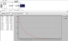
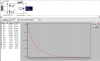
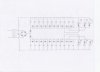
Attached are sim results for the bridge / FWCT / and doubler supplies using the 4-coil hypothetical ideal transformer. Initial current draw is 100mA, final current draw is 150mA. The FWCT in PSUD requires that I specify half of the coil as input, hence the 100V-32R vs. 200V-64R. I am also cheating in that I'm not accounting for primary resistance. And, pardon if these look squirrely - I run a Windoze emulator on my Mac :D

Please note, however, that if you cut the DCR of the FWCT transformer in two, it becomes equivalent to the bridge-rectified supply. But, if you are holding an Antek power transformer wondering what to do with the two coils in your monstermonoblock, my advice would be to parallel them and use a bridge-rectifier instead of a series FWCT. :)
 

Attachments

  • Screen shot 2009-10-22 at 8.02.10 PM.png
    Screen shot 2009-10-22 at 8.02.10 PM.png
    35.4 KB · Views: 27
  • Screen shot 2009-10-22 at 8.02.49 PM.png
    Screen shot 2009-10-22 at 8.02.49 PM.png
    32.4 KB · Views: 19
  • Screen shot 2009-10-22 at 8.03.29 PM.png
    Screen shot 2009-10-22 at 8.03.29 PM.png
    34 KB · Views: 17
Last edited:
Hi All, Sorry I was away I had to think about this one and do a little consulting with an Engineer and Tech I work with but due to modern switching supplies they were a bit to rusty on transformer theory claiming what jon was presenting here was over their heads with out studying it at length which they did not have the time.

Myself, I have had a family medical emergency this week with a niece and family is in from out of state many which I haven't seen in yrs.

So on with the show :lurk:

OH, I am suggesting that the doubler transformer might have ~1/4th the DCR of a typical non-CT transformer used with a bridge rectifier, and ~1/16th the DCR for an equivalent full-wave CT transformer.

Ok so this is how I see this working comparing apples to apples, If I imagine we have a 100VA rated transformer and it has 2-50 volt windings at 50VA each and at 16 ohms each we can use this in two full wave rectified ways.

One we can use a pair of diodes and run a center taped configuration.

This gives us 16 ohms DCR on each leg which the supply sees one at a time.

Next we can use a bridge rectifier and parallel the windings which gives a nice 8 ohm DCR

Now if we do as you suggest use a doubler circuit.

It finally came to me this morning for the 1/4th after drawing it out, keeping the same VA rating of the transformer. I imagined folding the paralleled 16 ohm 50 volt windings with is already at 8 ohms for a 25 volt winding at the same VA would be just 4 ohms! which would give us 1/4 th DCR

:scratch2:And thats pretty incredible really when I think of it's potential dynamically :thmbsp:

Nothing like a little time for it to sink in :D

But as to the 1/16th with 4-16 ohm DCR taps perhaps I have a block again but I'm not seeing it unless your looking at your 64 ohm full DCR of a full-wave CT from end to end. Which electrically is not seen it would be 32 ohms.

What I need to see is the same DC voltage being able to be produced at the same VA level.

Perhaps you could explain this?

Drawings might help with DCR's of coil sections perhaps VA's of each section as well?


This is just in terms of coil DCR for approximately equal dissipation, not apparent resistive contribution to supply impedance, not accounting for core differences, not accounting for the primary coil resistance, and I'm certainly not factoring in cost :thmbsp:

Imagine a hypothetical transformer with 4x 16 ohm coils at 50V each. In one case, you can form a series total 64 ohm 200V FWCT coil, in another a 16 ohm 100V series-parallel combination for a bridge-rectified circuit, and another a 4 ohm 50V paralleled coil for a doubler circuit. So this is a hypothetical transformer that can do it all. :smoke:

With large enough input capacitors, the doubler will perform very similarly to the bridge rectified circuit - both in terms of time constant and overall impedance (within a diode's drop of each other), but the FWCT will exhibit approximately twice the resistive supply impedance contributed by the PT than in the more efficient bridged and doubled supplies. The halved DCR contribution is offset by a factor of 4 increase in DCR -- likewise, the doubler's quadrupled DCR contribution is offset by a factor of 4 reduction in DCR compared to the bridge supply.

Since the doubler requires better / larger caps, and almost certainly a custom power transformer, I view it (today) as a "luxury" item when it is designed to equal other supplies - it is (IMHO) a safer supply in terms of voltages involved, and should be more reliable if designed for equal output.

Attached are sim results for the bridge / FWCT / and doubler supplies using the 4-coil hypothetical ideal transformer. Initial current draw is 100mA, final current draw is 150mA. The FWCT in PSUD requires that I specify half of the coil as input, hence the 100V-32R vs. 200V-64R. I am also cheating in that I'm not accounting for primary resistance. And, pardon if these look squirrely - I run a Windoze emulator on my Mac :D

Again jon, I need comparisons with same DC voltage produced with the same VA rating.

Please note, however, that if you cut the DCR of the FWCT transformer in two, it becomes equivalent to the bridge-rectified supply. But, if you are holding an Antek power transformer wondering what to do with the two coils in your monstermonoblock, my advice would be to parallel them and use a bridge-rectifier instead of a series FWCT. :)

This of course I agree with, and is very good advice.

Thanks jon :thmbsp:

SET12
 
But as to the 1/16th with 4-16 ohm DCR taps perhaps I have a block again but I'm not seeing it unless your looking at your 64 ohm full DCR of a full-wave CT from end to end. Which electrically is not seen it would be 32 ohms.

First, I apologize if my post was a bit condensed and rambling :D And I'm assuming the primary is lossless, which is not the case, but it makes my example easier!

So, (where "||" = parallel, "+" = series)

In the doubler case, you have 16 || 16 || 16 || 16 = 4 ohms

In the bridge case, you have (16 + 16) || (16 + 16) = 16 ohms.

In the FWCT case, you have 16 + 16 + 16 + 16 = 64 ohms.

Yes, you are right, electrically the FWCT supply "looks" like 32 ohms in practice, although the coil is 64 ohms.

The bridge rectified supply "looks" like 16 ohms, and the coil is 16 ohms.

The doubler "looks" also like 16 ohms, but the coil is only 4 ohms.

In summary, the doubler and bridge can be nearly equal (tiny advantage to bridge), and outperform the FWCT if the rest of the transformer design is equal. The FWCT requires a proportionately "bigger" transformer to match the bridge (in this case, the coil would need to be 32R instead of 64R). The doubler requires more capacitance, and better quality capacitance.

This may be my last post for a while - I'm in an airport preparing to disappear for a week!
 
First, I apologize if my post was a bit condensed and rambling :D And I'm assuming the primary is lossless, which is not the case, but it makes my example easier!

So, (where "||" = parallel, "+" = series)

In the doubler case, you have 16 || 16 || 16 || 16 = 4 ohms

In the bridge case, you have (16 + 16) || (16 + 16) = 16 ohms.

In the FWCT case, you have 16 + 16 + 16 + 16 = 64 ohms.

Yes, you are right, electrically the FWCT supply "looks" like 32 ohms in practice, although the coil is 64 ohms.

The bridge rectified supply "looks" like 16 ohms, and the coil is 16 ohms.

The doubler "looks" also like 16 ohms, but the coil is only 4 ohms.

In summary, the doubler and bridge can be nearly equal (tiny advantage to bridge), and outperform the FWCT if the rest of the transformer design is equal. The FWCT requires a proportionately "bigger" transformer to match the bridge (in this case, the coil would need to be 32R instead of 64R). The doubler requires more capacitance, and better quality capacitance.

This may be my last post for a while - I'm in an airport preparing to disappear for a week!

Great post, and congrats on 1k.:thmbsp:
 
I just remembered the power supply in this amp. It a single ended triode strapped 6CA7 job that makes about 7 watts a side. A big old PT out of a 40 watt organ tone cab. runs into two 5R4s that feed two big motor runs, then a custom wound Heyboer choke and two more motor runs. I've been meaning to get rid of those big bleeders down there and see what happens. This is the first amp I ever built.:D
 
Last edited:
I just remembered the power supply in this amp. It a single ended triode strapped 6CA7 job that makes about 7 watts a side. A big old PT out of a 40 watt organ tone cab. runs into two 5R4s that feed two big motor runs, then a custom wound Heyboer choke and two more motor runs. I've been meaning to get rid of those big bleeders down there and see what happens. This is the first amp I ever built.:D

Jay, I'm sure I'm not the first to say this but :D that is one nice looking amp and I like what you did with the attenuators, I take it the switch is for muting?

I really like its Retro look and of course there are any number of tubes in the EL34 family you could probaly use in that circuit. :yes:

Thats a great job :thmbsp:

SET12
 
Supply Drawings with Explanations

I was in another supply discussion and posted this in a thread. But thought it ought to be posted here as this is what I wanted to get to.

Thanks to all that took an interest!

SET12

But a number of yrs ago I fooled around with supply designs and built monster supplies like this one but its not easy to make something like this sound good and normally to much capacitance sounds bad :tears: but I'll tell you about how I made it good :D and as fast as a 40uf poly prop

The two supplies work together. 11,000uf's @ 400VDC 900 Joules of Energy.

Phono%20Stage%20complete%20Tube%20Section.jpg


Phono%20Stage%20Power%20Supply-th.jpg


Below are two supply diagrams that I have used in the above phono stage and a stereo power amp. I use similar isolation with with my monoblocks

phonosupply.jpgdiodeisolationsupply.jpg

If one wants, one can also use chokes with this say just after a rectifier tube. I learned about this from an early 1960's solid state design manual. The engineer quoted some 80db of isolation between channels for a stereo amplifier that used one transformer and individual channel supplies. I put two and two together and made a discovery by accident. Its a long story.

Any number of combination's are possible. I included the tube rectifier as it is the most like my monoamp's but without the last 4 didoes.

You might think that there must be some sort of signature but there is not to my ears anyway. In my power amps last caps are Aeon Polyprop's, the amps sound as though the 1800uf's weren't even there! Its as thought the diodes preserve the sound of the last cap you are using and in my case all the transparency and speed of the small 40uf caps.

So how does it work?

Looking at tube rectifier version one could use either one of the last caps for their first power stage and the other for their driver stage. Imagine a power tube depleting its final cap. looking at the second final cap you can see that there is noway that it could be charged because it has its own blocking diode. Same goes for the driver cap. Now when they are discharged think of the attraction of the rest of the supply as a pull up!

Looking at the phono yeah, that's a monster and if you think no one uses anything this big think again! The Aesthetix Io Phono Stage uses a supply of equivalent size. Which I have heard is dark sounding! and that's what I would hear if I didn't come up with this trick See the green caps in the large picture? Well those bypass 10 diodes they are 47uf Muse Bipolar caps and I thought the supply sounded just awful without them! So when the pie gets long these do the trick and again the monster supply sounds like individual 40uf Aeon Polyprops! Just as transparent as though the 5500uf's/channel of electrolytic were not even there.

So whats the benefit?

Sheer speed transparency and dynamics beyond any $1000 phono stage I have ever heard. And when talking about speed the DCR path is essentially the transformers. One other note. Know the EAR 834P, well it sounds kind of dark to me and slow. So why is that? Well I have its schematic and the first gain stage is feed from a cap that is feed from a 100K pie resistor. So my thought is that it has to long of a time constant which makes it sound slow and dark to my ears.

So this is how my gear gets it's slam and transparency.

SET12 :thmbsp:
 
Last edited:
What's a pie resistor? And can I get mine with Ice Cream? ;)

:lmao: Now that's funny!

For those that are new to DIYing Pie Resistors are for dropping the noise of a supply over. But in this case of my supplies the noise is dropped over the diodes with a cleaner DC supply after each stage of the supply. In the case of my phono supply its dead quiet and that's with 66db of gain. The phono was a complete old school scratch design with no computer assistance other than a hand held calculator.

SET12
 
really glad you posted that

I was really glad you posted the post note schematic and pics at the end of this thread.

I was really not keeping up with your massive cap and diode references, and it helped a lot.

I would say though, I enjoyed the push to try other power supply designs. We all have our favorites, and this has me thinking that maybe a complete rework of one of my PA Frankenstein amps may be in order.

I had been thinking about just working with the original set up, but since it does not really work . . . why not try a different setup!

By the way, what year did you build that phono setup?

:)

Dan
 
I was really glad you posted the post note schematic and pics at the end of this thread.

I was really not keeping up with your massive cap and diode references, and it helped a lot.

I would say though, I enjoyed the push to try other power supply designs. We all have our favorites, and this has me thinking that maybe a complete rework of one of my PA Frankenstein amps may be in order.

I had been thinking about just working with the original set up, but since it does not really work . . . why not try a different setup!

By the way, what year did you build that phono setup?

:)

Dan

Dan,

Yes, I was side tracked for a while a new big thread on my beautiful sounding new Bob Crites Klipsch Midrange's along with installing grid choke and anode chokes in my amps man what a difference! and working 6 days a week. I knew I had to draw it out as I don't have any electronic CAD software. It was just when I was discussing heekma's 811A Power Supply and he's seeing some of the light that I see, and I had to show him the design ideas I have worked with and I just sat down and drew out the phono supply in pencil and lucky enough the scanner was able to read it good enough.

Whats a PA Frankenstein Amp? And do you have a schematic for it?

If its a PP they are easy to pull better dynamics from because of the cancellation of noise from PP. Hopefully they are capacitor input and not choke input supplies which have higher DCR paths.

The Phono was built about 10 yrs ago or so. Jim White and his Io Phono inspired my design, along with J.C. Morrison. from (Sound Practices Magazine) and Arthur Z. Loesch have greatly inspired me as well as Jeff Medwin who is a very controversial designer, his work parallels mine.

http://www.tempoelectric.com/faq.htm

I have just ordered some low DCR chokes which are 3.5 ohms and .3H the few ohms here shouldn't effect my amps dynamics yet it should kill about 50% of my current supply noise so I'm going to listen to them. But as I think about it the Phono Supply Method may really be the answer in the long run perhaps!

Use more supply sections and then bypass the diodes with caps to get the transparency back that is likely a better answer IMO cause the Phono is so dead quite! And very,very powerful.

BTW I did visit your web site. You have a very nice home. Love the view!!

I saw that you have a BS in Electrical Engineering. That's great! as its easier to converse on theory.

SET12
 
New Concepts Being Used

Hello, to those that have had an interest in alternative power supply design and have followed this thread.

Thought I would give an update on my own thread. As I have pretty much completed a 45 monoblock of what I would consider some of the most cutting edge design thinking that I have come across after being given some access to an Electrical Engineers work on Low DCR, Low Energy Storage Chokes Research.

I combined this with my own work with diode decoupling that I first saw used in this 1961 Transistor Design manual.

http://babel.hathitrust.org/cgi/pt?view=image;size=100;id=coo.31924004610006;page=root;seq=142;num=132

The design fascinated me as I saw it could be used in a # of ways

The design below is for a decoupled isolated negative supply. Which the designer claims is greater than 80db.

gediodeisolation.jpg


I have used diode decoupling with much success for the better part of 15yrs.

My latest work centers on using Chokes in a way that is meant to compliment capacitors instead of hindering them with large chokes.

Music has peaks and valley's and the supply needs to move energy.

So the use of low DCR chokes with Low Inductance is a way of enhancing the supply cap.

As the supply cap depletes it asks for current, the problem is so does the tube. And more often then not the cap gets it.

ampsupplyimpedance.png


As many may or may not know the more a cap is depleted the lower its internal resistance will be. So basically a cap at turn on is basically a short.

So the trick is to buffer the cap.

And for that a Low DCR Low Inductance choke is preferred, Why?

Because a choke has a core with flux and windings it creates a grip on current flow and doesn't want to give it up!

Its the nature of the choke. So when a choke has low storage it has less gripe and when the cap calls for current the choke coverts the flux very fast to current for the cap and along with low DCR you get fast time constants for charging.

The process made a lot of sense to me.

And with the use of diode decoupling it could be maximized by blocking the discharge of the large caps but allowing them to aid in pulling up the small caps as when the cap inductor combo is pulled down the diode turns on creating a charge attraction to the larger cap reserve, its this attraction along with a low DCR path that gives my own amplifiers or the 45 that I designed such authority that people tend not to forget.

In the case of John's 45 amplifiers he wanted some of this authority and asked if I could design him such amp with the 45 in mind.

2yrs later, $3000 in parts with 160hrs of labor we came up with such a design.

BOS Power Supply.jpg

Its a partial schematic as I am awaiting a newly drawn one which will include the new 6D22S Bridge rectifiers with dual paralleled Antek power transformers.

A list of some of the parts.

Chokes are by Hammond

L1,L2 193R .3H 3.5 Ohm's

L3,L4 193U .2H 1.7 Ohm's

L6 Valab 200H Anode Choke for the 12BH7

L5 Silk Grid Choke used in step up mode

C2,C3 are composed of various size Electrolytic caps totaling 947uf/each

C9 34uF Amp Ohm Oil

C10 24uf Amp Ohm Oil

D7-D10 are LED's used for biasing the 12BH7 with a Muse 470uf bypass

T6 Output Transformer James 6123N using the 3.5K loading

The DCR of this amplifier not including the rectifier tubes is but a mere 10 ohm's

The power transformers are rated at 400VA total and have a 5 ohm secondary winding. Many tube power transformers 10 times or more higher.

What this means is the typical amplifier with SS rectifiers and typical chokes maybe able to move 500mA or so.

In contrast the BOS45 supply if it was using a SS rectification it could move 12,000mA. But its using a bridge tube rectifier, but even with the tubes it still has a capacity to deliver 5000ma though the tubes though they would be destroyed trying to conduct this. The point is the impulse DCR is low.

Certainly one could say its sheer overkill, and I would say yes, but is it heard? We think so!

I was able to hear the project the first time while attending AKfast 2012 and I was really taken back what I heard from this 1.8 watt amplifier. It sounded literally stress free, with detail, body and authority I never knew was possible. I think most people would wonder what can be had from 1.8 watts? All I can respond with is "hearing is believing"

SET12
 
A good portion of the difference you hear when removing the 100 ohm resistor has to do with raised B+.... I bet more then the actual lower resistance in the power supply. 20 volts or so extra on every stage of the amplifier will indeed have an effect to the sound.

200 uf on the 5AR4 is a sure path to quicker death of an expensive Mullard... it will work but sooner or later it will arc over much depends on how much and type of use it has had before the modification. Those tubes are tough...but you are taking life away from it every time you turn the amp on. The stress is at turn on not while running it. If you think long and hard about that fact you will find the answer as to why the difference you hear has more to do with the raised voltage the the resistance removed from the power supply.

Put a sovtek 5AR4 in the amp and it will shock me if you get 3 months out of it if you use the amplifier much.
 
In the interest of continuing conversation here, in the correct thread...

An idea I've come to like more recently is that you can go with Dans brute force approach here and definitely get the benefits of minimizing DCR in the supply...but another option exists for the minimalists out there.

With the 193R chokes listed above.... about .3 henry and 3.5 ohms DCR... you don't get much isolation between stages. Dan add's diodes there to fix that...in absence of that I've found that the $10 Triad C40X .32henry 10 ohm is a bit easier to work with when using much less C in the supply.

The Hammond 159ZA is also .3 henry and 6 ohms... I found I liked it a bit better than the 193R...however it is open bracket....and only $27 each.

Hammond has a few more good offerings... a .6H at 11 ohms looks real good to me... and you can get 1.5H from them @ 25 or so ohms DCR.

Edcor is the current champ of budget LOW DCR GOOD chokes...2 henries, 21 ohms DCR and $31.


I think when you get a bit more resistance in the choke, around 10 ohms you get some advantages...Setup with 2 or 3 stages with .5 henry chokes you can use small caps and have another type of "low DCR" supply...Smaller caps, around 50uf maybe even upwards of 100uf can be film caps...and you can skip the slow warmup and bulk electrolytic all together.


When you get to the more "moderate DCR approach" you can use PSUD to tune the values in the order that works best...and end up with a supply that can do 80% or better of what the above does, with far less components.


Just another crazy out in left field approach to the same end. If you size the PT large enough the big bulk of capacitance isn't as necessary for some people.

Maybe a mod could change my tag to "low dcr troll"? :)


I've actually tested the Hammond 193R vs the Triad C40x vs the Hammond 159ZA.

With 100ma current draw in a KT120 SE amplifier I found the Hammond 193R buzzed as a "quasi choke input". The Triad C40x also buzzed. The Hammond 159ZA did not buzz.

In the second position in an LCLC supply the Triad C40x filtered the most, followed by the 159ZA and in last was the 193r. This was measuring noise, ac on the output transformer at idle with speakers connected.
 
Last edited:
A good portion of the difference you hear when removing the 100 ohm resistor has to do with raised B+.... I bet more then the actual lower resistance in the power supply. 20 volts or so extra on every stage of the amplifier will indeed have an effect to the sound.

200 uf on the 5AR4 is a sure path to quicker death of an expensive Mullard... it will work but sooner or later it will arc over much depends on how much and type of use it has had before the modification. Those tubes are tough...but you are taking life away from it every time you turn the amp on. The stress is at turn on not while running it. If you think long and hard about that fact you will find the answer as to why the difference you hear has more to do with the raised voltage the the resistance removed from the power supply.

Put a sovtek 5AR4 in the amp and it will shock me if you get 3 months out of it if you use the amplifier much.

I can't quite recall what I was working with for voltage maybe around 15 VDC I revisited this effect with the same person I did the first time I heard more than 15 years ago because someone else declared the same thing.

I don't have to think long and hard I listened, I used a Variac to lower the B+ back to the original value and we heard the same effect of macro and micro dynamics being enhanced.

That friend has some of the best ears I have ever known someone to have. He is both a musician and audio buff that often listens to live music of all sorts several nites a week. And as he said frankly the amplifier with that 100 ohm resistor was enough to put him asleep while without it was engaging and I concurred.

Yes I'm familiar with Sovek 5AR4's and know their slow turn on does not meet NOS spec's and they very well will arc over. Even with other directly heated rectifiers the turn on varies substantially.

I'll bet later for a 5AR4 as I use a GZ37 and it has a larger voltage drop as you know. It took 5yrs of nearly every day playing for that tube to have a 20% loss of emission and that was with a 600uf input running @500VDC B+ and the additional 1200uf used done line. The loss is acceptable considering what the performance is for me. I'm to old to care about a rectifier lasting 30yrs by giving it kind treatment, its meant to serve me not me it and that it does. But I can understand your wanting them to last longer being a manufacture. And there is nothing wrong with that.

I love the GZ37 sound but now a day's they are pricy as well as NOS 5AR4's, I would rather listen to a GZ37 then a 5AR4 typically in SET's, PP isn't as much a factor to me although I know of people still preferring the GZ37 over the 5AR4 for PP. I'm not the first to use high volume capacitance with the GZ37's Here Cary Audio used them for years. Here for example where the first cap is 1100uf

cary807amp.jpg

And I think after the experience with tube bridge rectifiers I'm going to be able to live with damper diodes which give 30 seconds or more of turn on delay. So 5yrs or 20% loss and I replace, and these will be relatively inexpensive.

SET12
 
Last edited:
I like the 37 too, and it's a good looking tube as well. They are getting pricey though. All of the ones I have are Mullards, did anyone else make them?
 
I can't quite recall what I was working with for voltage maybe around 15 VDC I revisited this effect with the same person I did the first time I heard more than 15 years ago because someone else declared the same thing.

I don't have to think long and hard I listened, I used a Variac to lower the B+ back to the original value and we heard the same effect of macro and micro dynamics being enhanced.

That friend has some of the best ears I have ever known someone to have. He is both a musician and audio buff that often listens to live music of all sorts several nites a week. And as he said frankly the amplifier with that 100 ohm resistor was enough to put him asleep while without it was engaging and I concurred.

Yes I'm familiar with Sovek 5AR4's and know their slow turn on does not meet NOS spec's and they very well will arc over. Even with other directly heated rectifiers the turn on varies substantially.

I'll bet later for a 5AR4 as I use a GZ37 and it has a larger voltage drop as you know. It took 5yrs of nearly every day playing for that tube to have a 20% loss of emission and that was with a 600uf input running @500VDC B+ and the additional 1200uf used done line. The loss is acceptable considering what the performance is for me. I'm to old to care about a rectifier lasting 30yrs by giving it kind treatment, its meant to serve me not me it and that it does. But I can understand your wanting them to last longer being a manufacture. And there is nothing wrong with that.

I love the GZ37 sound but now a day's they are pricy as well as NOS 5AR4's, I would rather listen to a GZ37 then a 5AR4 typically in SET's, PP isn't as much a factor to me although I know of people still preferring the GZ37 over the 5AR4 for PP. I'm not the first to use high volume capacitance with the GZ37's Here Cary Audio used them for years. Here for example where the first cap is 1100uf

View attachment 351888

And I think after the experience with tube bridge rectifiers I'm going to be able to live with damper diodes which give 30 seconds or more of turn on delay. So 5yrs or 20% loss and I replace, and these will be relatively inexpensive.

SET12


Using a variac to lower the voltage to the entire amp is a poor way to compare. You would be starving the heaters of the proper voltage, heater voltage does effect sonics. Let me repeat I did not say removing the resistor had no difference I said the majority of the difference was from the voltage rise to the entire circuit. I think your modification would be better served with the tube rectifier change you mentioned the GZ37 is a beast and would handle the increased load better. But if it was me I'd place a small cap say 2uf at the rectifier and then 10 to 20 ohms of resistance then the large reservoir for the center tap. I think if a true side by side "BLIND" comparison was done you and your golden ear friend would be hard pressed to hear a difference (nearly impossible in my opinion). I also suggest you do think long and hard about all of this the advice you give could be followed by folks that don't have the pure luck you have running things over specification.
 
Back
Top Bottom