• The move to the new server is done. There are some software and database maintenance updates in process. This has us passing the hat around to help out. We appreciate any donations. Seriously, even a dollar helps. The payment page may be found here - https://www.audiokarma.org/support.html

Vintage Fried Speakers, Indy

like this type of stuff


http://www.usafoam.com/acousticfoam/acousticfoam.html


Acoustic egg crate
eggcratefoam2.jpg


versus
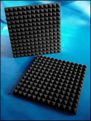
Acoustic Pyramid
pyramidfoam2.jpg


and unrelated but added just cause I thought they looked pretty cool

Studio Columns
studiocolumn2.jpg
 
:tresbon: :tresbon: :tresbon:

Mc ;-) i think i should take lessons in how to properly motivate without bullying from sm19422 :-P what a polite way to say .. take a few pics and you will have what you need ...

i feel so rude for my worthless without pics post now .. although .. i still think us less polite people still want to see how that foam is set in there

I do not understand why you claim I am bullying you in any way?:thumbsdn:

If the OP can find the review of the first Fried model Q it shows the stuffing density layout of the model R as an example of Fried's line tunnel enclosures.

The foam is placed in the line and not against the side walls of the enclosure.
There are pieces of foam that act as spacers between the sidewalls of the enclosure to keep the foam from shifting .
I have used liquid nails adhesive to glue the foam in place for 1/4 W T-lines and line tunnel enclosures I have built over the years. :)

Open cell low denisty polyurethane foam is what is used to dampen the back wave of the Kef B139 driver in the model R enclosure. If you replace the foam make sure that it is the flat kind.

I have purchased foam from fabric stores like Joann Fabrics.

Using fiberglass or acoustical egg crate foam will not achieve the proper damping of the line tunnel enlcosure. Fried used this type of foam in all his speaker enclosures.
 
SM19422, he's joking, he's implying that I'm an idiot for not just taking pictures and that you are gently bullying me towards that conclusion. A joke at my expense that I'll gladly take ;)

I took some photos and will post them for the edification of others of the foam and the crossovers which I jammed my camera deep into the morass of speaker phone to photograph.

I think I was able to decipher the cap values except for one that appears to be hidden by foam in the very bottom left corner. I am also unsure what the huge black object horizontally across to top of the xover is but after viewing the photos...it looks like this may be a PCB plugged into an edge connector that I could literally yank from the edge connector and remove as a whole? Anyone else recapped an R that can confirm?

John
 

Attachments

  • 2013-11-11 20.26.12.jpg
    2013-11-11 20.26.12.jpg
    198.8 KB · Views: 82
  • 2013-11-11 20.27.14.jpg
    2013-11-11 20.27.14.jpg
    155.2 KB · Views: 30
  • 2013-11-11 20.27.53.jpg
    2013-11-11 20.27.53.jpg
    153.5 KB · Views: 27
  • 2013-11-11 20.28.22.jpg
    2013-11-11 20.28.22.jpg
    219.1 KB · Views: 108
actually neither of you are correct .. i was implying that sm19422 had such a helpful and encouraging way of saying if there were pictures he could help. my lame butt just posted the this thread is worthless ..

sm19422 :-) my implication was that your reply was in fact helpful and so nicely done that i was a little embarassed (as offten happens when crass meets a class act :0)

To add to that .. given how confusingly I veiled the compliment(aka i made it sound like the opposite of what i meant) ... and your very polite reaction in spite of probably thinking much worse than a thumbs down to me .. .. you have reinforced that initial impression

thanks for going easy on me :-) and thanks for all the good info!
 
The foam lining the tunnel in the Qs is a block of white foam (the exposed side of which yellows over time). My memory of the As is foggy, but I think either the exposed side of the foam was spray painted black, or maybe it was all black -- it was so crumbled that I got rid of it and replaced it with what I hoped was close to the correct density. It's a tight fit -- no air can move in or out without passing through the full length of the foam.
 
Not sure if you guys saw my attachments but they show the awesome maze of foam. I'm hoping to god that what I spy through that hole is that the crossover is terminated in some type of edge connector (the blue object) and that I can pull it loose and take the entire PCB out.
 
John .. i think i would use a perm marker .. number the foam in place, take another picture :-)

it does look like the foam is notched to help reassemble but you may want to in addition to the numbering, mark up a printed out picture of that numbering scheme with the measurements of where things came from ..

eg from bottom to center of first foam "beam" and mark x.x inches on center type of thing

Like the same picture you have here only numbered

attachment.php
 
SM19422, he's joking, he's implying that I'm an idiot for not just taking pictures and that you are gently bullying me towards that conclusion. A joke at my expense that I'll gladly take ;)

I took some photos and will post them for the edification of others of the foam and the crossovers which I jammed my camera deep into the morass of speaker phone to photograph.

I think I was able to decipher the cap values except for one that appears to be hidden by foam in the very bottom left corner. I am also unsure what the huge black object horizontally across to top of the xover is but after viewing the photos...it looks like this may be a PCB plugged into an edge connector that I could literally yank from the edge connector and remove as a whole? Anyone else recapped an R that can confirm?

John

The large horizontal black object that is tubular is an iron core wire wound inductor, most likely for the woofer, you can just see the red coated magnet wire of the inductor peeking out on the right side top of the picture. There are two air core inductors on white bobbins at slight angles to each other on the left side of the crossover. At the bottom, it does indeed look like there is some type of blue edge connector but I am not familiar with how Fried did his crossovers to confirm this. I don't see any particular screw mountings though on the the circuit board so you might be able to rock it gently side to side to see if it comes loose.

But very importantly, you should be tracing the wires to each driver and label each with polarity or terminal (driver and wire) so that you know EXACTLY how they wire back up, pics here will also help.

I know you've recapped crossovers before, it's just a reminder. Been there, done that (or forgot to do that), got the T-shirt.

Plenty of NP electrolytics on there, I suspect the yellow Seacor film caps are likely Mylar polyester caps. For most of us, the recommendation is to change like for like types. There are those who suggest changing out Electrolytics for film IF the sizes allow and fit, would be an interesting exercise to do one side with electrolytics and the other side with films where possible and then see how they sound.

Lots of discussion on that issue.

attachment.php
 
That makes total sense, I do see the tinned wire of an inductor poking out on the right side. I was just thrown by the cover over the actual wound copper. What I made note on the blue edge connector was that all of the wires that lead to the drivers terminate on this edge connector leading me to believe that I could get the crossover PCB out without disconnecting or dealing with any of the wires that lead to the drivers. I looked for screws as well and didn’t see them so I kind of assumed that the crossover was held in only by the edge connector and the edge connector is fastened to the terminal plate which DOES have screws. Also of note, the wires were soldered into the woofer and perhaps may be on the other drivers as well. This made it no fun to get into the lozenge shaped hole because there wasn’t enough slack for me to actually set the woofer down on the surface below the cabinet. Your suggestion is totally valid regarding documenting the color scheme of the wiring, what I usually do is remove each driver and take a digital picture of the back of each terminal in order to make note of what color wire feeds each driver and where they connect.
Your reminder is valid, I’ve done a ton of crossovers but this one is very different and each one has presented it’s challenges.
Agreed, lots of NPE on there but of values high enough that I’m going to replace them with like NPE’s in most cases considering that 33 and up is more than I’d spend on a poly cap. 10uf is even marginal and considering it’s a PCB with limited space a large 10uf poly cap would be tough to get on the board…I know I could do it but I would probably have to have it hovering with long leads off the PCB and make no SQ difference. The seacor caps agreed are mylar like in the DQ-10, I would probably replace those with 3 or 5% metalized poly caps unless you believe that the mylar should be left in place…from my understanding they are non-degrading caps but there might be something to be gained by going to film caps.
 
McCarthy ... your tag lists:

Primary Systems HT Room: AR9, DQ-10, Klipsch Chorus, Infinity RSII, ADS L1590 (Emotiva XDA/Yamaha M-80/Yamaha PC2602)


Do you still have a DQ-10 or did you off load that and pick up the 20?
 
I have both. I was going to sell my 10's but after I had a bunch of great ak'ers over a few weeks back they pretty much unanimously said the 10's were their favorite out of my entire collection so I pulled them from the market. The whole system takes up a lot of space unfortunately as I have the bass module and passive xover.

Sent from my SPH-L710 using Tapatalk
 
I'd like polypropylene caps instead of the mylars, but that's me. Metallized or film and film PP caps would be fine.
 
I'd like polypropylene caps instead of the mylars, but that's me. Metallized or film and film PP caps would be fine.

I agree, that's what I usually do is replace any lower value caps with metallized poly caps. Erse Audio caps are so dirt cheap that it's not worth passing it up, you can get 3% caps for cheaper than Dayton's. They also do like $1.99 us postal shipping for small orders where they just send the caps in a padded envelope.
 
Also I'm not sure if the IMF sound is close to what I'm hearing out of my model R but there is an IMF Studio Monitor on craigslist in Napier Illinois.

What speaker in the IMF line is lateral from the Fried Model R i.e. what is it equivalent to within the IMF lineup?
 
Okay, after removing foam we're all good, looks like it's 4 screws and remove from the edge connector and it's recap time.

Full cap inventory for Fried Model R:
1 x 50uf 50v NPE

3 x 33uf 50v NPE

2 x 10uf 50v NPE

2 x 4.7uf 250v Mylar

Removed some foam and have some better xover photos, might as well document this in case someone else has to replicate work.
 

Attachments

  • 2013-11-12 17.40.00.jpg
    2013-11-12 17.40.00.jpg
    212.1 KB · Views: 18
  • 2013-11-12 17.40.28.jpg
    2013-11-12 17.40.28.jpg
    172.9 KB · Views: 13
  • 2013-11-12 17.41.09.jpg
    2013-11-12 17.41.09.jpg
    185.5 KB · Views: 13
The large horizontal black object that is tubular is an iron core wire wound inductor, most likely for the woofer, you can just see the red coated magnet wire of the inductor peeking out on the right side top of the picture. There are two air core inductors on white bobbins at slight angles to each other on the left side of the crossover. At the bottom, it does indeed look like there is some type of blue edge connector but I am not familiar with how Fried did his crossovers to confirm this. I don't see any particular screw mountings though on the the circuit board so you might be able to rock it gently side to side to see if it comes loose.

But very importantly, you should be tracing the wires to each driver and label each with polarity or terminal (driver and wire) so that you know EXACTLY how they wire back up, pics here will also help.

I know you've recapped crossovers before, it's just a reminder. Been there, done that (or forgot to do that), got the T-shirt.

Plenty of NP electrolytics on there, I suspect the yellow Seacor film caps are likely Mylar polyester caps. For most of us, the recommendation is to change like for like types. There are those who suggest changing out Electrolytics for film IF the sizes allow and fit, would be an interesting exercise to do one side with electrolytics and the other side with films where possible and then see how they sound.

Lots of discussion on that issue.

attachment.php

Later models of the Fried line used air core inductors with 14 gauge wire for the woofers and subwoofers. He ised 18 gauge wire on all his midbass drivers since he needed the added Re. in the crossover circuit.
He continued to use electrolytic caps bypassed with poly caps.

It got to the point with the kits Fried sold that the buyer had to purchase their own crossover parts.
 
John,

I'm no IMF guru, but I don't believe they marketed a direct equivalent of the Fried model R. Those IMF's in Chicago you mentioned have been listed on CL for a very long time and have since gone down in asking $$. I have been hoping to find a pair of IMF TLS-50 MkII's locally, but the closest I have seen were in Columbus, OH. Above the TLS-50's were the TLS-80 MkII's and the TOTL RSPM (Reference Standard Professional Monitor) MkI, MkII, MkIII, MkIV.

Here's a short thread about the model R's and the IMF's:
http://audiokarma.org/forums/showthread.php?t=472066

Brad
 
Later models of the Fried line used air core inductors with 14 gauge wire for the woofers and subwoofers. He ised 18 gauge wire on all his midbass drivers since he needed the added Re. in the crossover circuit.
He continued to use electrolytic caps bypassed with poly caps.

It got to the point with the kits Fried sold that the buyer had to purchase their own crossover parts.

So from what I can tell the only difference between series I and series II was the crossover but since a PCB was used I'm guessing there's no guide or ability to modify the xover to become a series II. It also sounds like Fried was all over the place with the xovers.

I ordered my caps so I guess at this point I'll just opt for a one for one replacement. Was the Model R the TOTL Fried speaker for that timeframe? Where did it sit in the hierarchy?
 
John,

I'm no IMF guru, but I don't believe they marketed a direct equivalent of the Fried model R. Those IMF's in Chicago you mentioned have been listed on CL for a very long time and have since gone down in asking $$. I have been hoping to find a pair of IMF TLS-50 MkII's locally, but the closest I have seen were in Columbus, OH. Above the TLS-50's were the TLS-80 MkII's and the TOTL RSPM (Reference Standard Professional Monitor) MkI, MkII, MkIII, MkIV.

Here's a short thread about the model R's and the IMF's:
http://audiokarma.org/forums/showthread.php?t=472066

Brad

I read the same thread, I'm just trying to determine how close the IMF's sound like to the Fried Model R and determine what within the IMF line would be a lateral move versus an upward move. It's possible that the TLS-50's would be lateral potentially but I have no idea. Columbus isn't that far to get a pair of TLS-50's, if you ever wanted to drive out there I'd be game to ride with you if nothing else was going on. I have read the hierarchy of IMF speakers in other threads (these things have sounded so good that it's resulted in a quasi-obsession with IMF now). The pictures of the ones in Napierville unfortunately have no grill-off photos.
 
Back
Top Bottom