• The move to the new server is done. There are some software and database maintenance updates in process. This has us passing the hat around to help out. We appreciate any donations. Seriously, even a dollar helps. The payment page may be found here - https://www.audiokarma.org/support.html

Yamaha A-6a / A-760II No power

Levi8000

New Member
Hi everyone a couple of weeks ago I got a Yamaha A-6a (Japan version of the A-760II) and it has no power!
I opened it up and replaced all the capacitors on the main board, the B supply voltage was only 1.4v all the voltage readings coming off of the power supply board are fine. Except the optocoupler current is not right, I figured that was normal because the supply voltage is probably was too low for the optocoupler to switch on. I checked the output transistors and driver transistors for shorts, all good.

I notice when I short the transistor inside the optocoupler the unit powers up and draws an amp or so, the lights come on. Didn’t test for sound, but the B voltage reads correctly.
 
Register to hide this ad
Hi everyone a couple of weeks ago I got a Yamaha A-6a (Japan version of the A-760II) and it has no power!
I opened it up and replaced all the capacitors on the main board, the B supply voltage was only 1.4v all the voltage readings coming off of the power supply board are fine. Except the optocoupler current is not right, I figured that was normal because the supply voltage is probably was too low for the optocoupler to switch on. I checked the output transistors and driver transistors for shorts, all good.

I notice when I short the transistor inside the optocoupler the unit powers up and draws an amp or so, the lights come on. Didn’t test for sound, but the B voltage reads correctly.

Hi, welcome to the forum …
Could you please post a photo of what you’re looking at so everyone can clearly see? That’d be very helpful. Are you using this through a transformer?

Is it the SMOR5G thyristor you’re referring to? Also, I’d reflow all the solder joints in that section and preferably everywhere else before getting any deeper. Often that solves many connection, cold solder, dry solder related issues.
 
Is it the SMOR5G thyristor you’re referring to?
No. He is refering to the TLP508 optocoupler

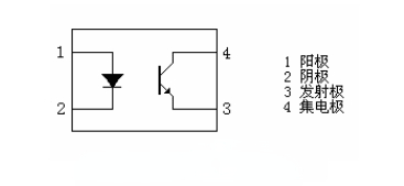
PC817%E5%86%85%E9%83%A8%E6%A1%86%E5%9B%BE.jpg

I notice when I short the transistor inside the optocoupler


DSC_0763_4624568.JPG
 
Last edited:
The optocoupler controls the amount ( phase angle) of input AC voltage applied to the power transformers primary via the Thyristors and SCR's.. You need to get the LED side of the optocoupler firing correctly.
 
Last edited:
Down load the B-6 service manual.. It has a pretty good " theory of operation " for these X-power supplies.

The M-50,M-70,B-6, A-760,A-760 II,A-960 & A-960 II all have the same X-Power supply.
 
Last edited:
I tried adjusting the optocoupler, is precision important just to get the thing to turn on? I turned the variable resistor all the way both ways then to half way, and I didn't notice any changes. I also checked that the variable resistor works.

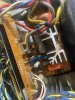
IMG_1742.JPG
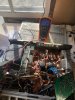
I was messing around with the amp today and I noticed that the traces for the positive and negative side of the dc power supply section of the main board are shorted together. as well as shorted to the AC going into the bridge rectifier. I pulled the bridge rectifier out, no shorts, diode drop seemed fine. I pulled the Filter caps both esr out fine, one reads dead short when the leads are flipped. The glue under the filter caps also corroded some jumpers, so I tried my best to clean that. I also checked the metal oxide resistors and zeners that, at first glance, look to be parallel with the filter caps. Not really to sure where to go from here, unless I missed something.

IMG_1741.JPG

Thanks again for your help everyone. This one has been a real head-scratcher for me. forgot to add, isn't the a-6a not a magnetic field style supply but the a-6 is?
 
I tried adjusting the optocoupler, is precision important just to get the thing to turn on? I turned the variable resistor all the way both ways then to half way, and I didn't notice any changes. I also checked that the variable resistor works.

View attachment 2694804
I was messing around with the amp today and I noticed that the traces for the positive and negative side of the dc power supply section of the main board are shorted together. as well as shorted to the AC going into the bridge rectifier. I pulled the bridge rectifier out, no shorts, diode drop seemed fine. I pulled the Filter caps both esr out fine, one reads dead short when the leads are flipped. The glue under the filter caps also corroded some jumpers, so I tried my best to clean that. I also checked the metal oxide resistors and zeners that, at first glance, look to be parallel with the filter caps. Not really to sure where to go from here, unless I missed something.

View attachment 2694805

Thanks again for your help everyone. This one has been a real head-scratcher for me. forgot to add, isn't the a-6a not a magnetic field style supply but the a-6 is?

Im assuming you’re following the SM for A-760ll?
CA9E64C9-64A0-4142-9331-D3A9F75A4371.jpeg
 
Last edited:
Precision is required when you’re setting the correct voltage of 1.2V +/-0.1 in conjunction with the supply voltage which is why it is best done with two multimeters. Turning the photocoupler on is not a precision job as far as I know from my B-50 which has the same mechanism, with the correct supply voltage it should come on when tweaked.

Supply voltages read fine?
 

Avionic, I can turn my photocoupler left and right and see voltage change without it dropping out. In my case, precision becomes an issue when I’m actually setting the correct voltages for both the supply and the photocoupler, gets jumpy. I get the same thing with the supply voltage, I can change it by many volts up and down without dropping out the photocoupler. In this case, it seems the photo coupler isn’t working to begin with. I can’t tell if there’s a voltage on the photocoupler which doesn’t change with varying pots or there’s no voltage to start with …
 
Last edited:
I’ll do the adjustment tomorrow and let you guys know whats going on. Is that 1.2v dc right? Optocouplers and Triacs are new to me.
 
Tried doing the adjustments but its no luck, the p1 is shorted to chassis ground.
F65E3BB8-70BD-4380-81BB-463DBD11857D.jpeg
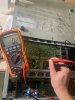
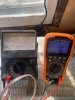
Right meter is reading for the Optocoupler adjustment, left is the B+, and B-. I figured that would happen considering the current draw on my variac is 0.02A. 1ECF3101-E7D4-4EA8-9907-D9B3B7D20716.jpeg
Did u mean to do the adjustments with the optocoupler shorted? If I remember, the unit draws current linearly when I do that. Its only 0.8A or so but i figured that is too high for an amp of this power rating.
 
Back
Top Bottom