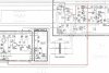
P1 should not be shorted to ground..!! Your negatve meter probe should be shorted to ground. The positive probe should be attached to P1..the p1 is shorted to chassis ground.


P1 should not be shorted to ground..!! Your negatve meter probe should be shorted to ground. The positive probe should be attached to P1..the p1 is shorted to chassis ground.

Does the service manual procedure tell you to short out the optocoupler ?
P1 should not be shorted to ground..!! Your negatve meter probe should be shorted to ground. The positive probe should be attached to P1..

Pulled out D501 , reads fine. Ill check the optocoupler later tonight. I checked the transistor in it but not the led, since I figured they hardly go bad. Checked all the line level stuff with my scope on the primary board other than the optocoupler.If you remove the photocoupler, do you still get a shorted P1? Have you checked D501?
With D501 removed, did you try to see if P1 still read a short?Pulled out D501 , reads fine. Ill check the optocoupler later tonight. I checked the transistor in it but not the led, since I figured they hardly go bad. Checked all the line level stuff with my scope on the primary board other than the optocoupler.
Great news …The unit is fixed! The chassis ground short was caused by a pretty embarrassing oversight. The mica sheet on one of the outputs was missing! Starts up nice now. Haven’t had the chance to use it yet. The infinity speakers I have need new woofers, which i’m waiting on. In the mean time, I was considering changing the op-amps, but it doesn’t really seem so worth it. Any suggestions?

You should not run any Japanese units on 120VAC, they’re not designed to operate on it.I was poking around in the amplifier to check the service manual adjustments, the amplifier was really hot, and I noticed the supply voltages were 54 volts! The big issue is that the variable resistor is at the very lowest. The optocoupler current is good. Do you guys have any advice? The unit is 100v running through a stepdown rated for 500w at 120vac.
Good, your initial description threw me. What voltage do you read on the optocoupler?Its not running on 120vac its running on 100vac through a 500w stepdown transformer. Vr303 is as low as it can be and the voltage is 54vdc, when on 120v it reads 60vdc.
1.2v, Also would rail voltage that high kill it? I changed all the caps with 105c ones, because I heard these ones ran hot.
If I had to give one serious advice, that’d be to remove the turntable and make sure nothing interferes with the air convection for your amp. Yamaha and all other manufacturers expressly warn about the danger and degradation it could cause to the amp operation. Also you’re slowly cooking your turntableAlright, thanks for your help. I’ll take a look. The heat dissipation problem is probably from the turntable on top of it having really low feet that block airflow.
 .
.
Lol the turntable was warm noticeably. Unfortunately I don't really have the table space for the both of them. The first sign I noticed of a major problem was the slight warp of a year old record. Would building a desk riser type thing above the amplifier with a couple of inches of clearance be wise?If I had to give one serious advice, that’d be to remove the turntable and make sure nothing interferes with the air convection for your amp. Yamaha and all other manufacturers expressly warn about the danger and degradation it could cause to the amp operation. Also you’re slowly cooking your turntable
Yes, give it a clearance of at least 4 to 5 inches (~10cm) each side, preferably more on the top side. It’s easy to build one out of wood. This is very important, please don’t take lightly.Lol the turntable was warm noticeably. Unfortunately I don't really have the table space for the both of them. The first sign I noticed of a major problem was the slight warp of a year old record. Would building a desk riser type thing above the amplifier with a couple of inches of clearance be wise?