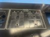
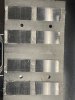
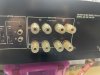
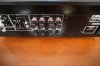
This is Part One of a comprehensive Yamaha B2 rebuild thread that is long overdue.
There will be subsequent parts within this thread since there is a limit of how many photos I can attach to each post.
There will be additional edits to this post for both content and syntax.
Abstract:
A fully upgraded B-2 offers a unique opportunity to own a vintage v-fet amplifier with all the modern features and reliability of a new amp. Leveraging today's technical advancements coupled with about 40+ years of data about the B-2, we can now take a great amplifier that is tired with age and return it to prime functionality or make it even better than when it left the factory floor.
The following details about the work I do with the B-2s are intended to share my opinions and experiences to hopefully help answer questions for other B-2 owners.
Some of the topics will involve radical modifications to the original components and / or design. At no point in time I claim that I know more than the Yamaha engineers did ~45 years ago, but merely have the ability to learn from what they have created, observe data collected by me and others over time, leverage the use of advanced computer aided design and better materials available today, to improve from where the Yamaha engineers left off.
WARNING:
Disclaimer:
Below is a High-level list of what I consider areas of opportunity for improvement for the Yamaha B-2 based on the order of importance / level of annoyance or functional criticality.
High importance (i.e. major PITA):
Miscellaneous (nice to have):
I intend to organize the order of topics aligned with the above priority list. Until I find the time to add details about each topic, the information below might seem uncoordinated with the list above, but it will eventually make sense once I am done adding and editing everything.
SELECTOR ASSEMBLEY
The selector assembly is a pain-point reported by most Yamaha B-2 owners and for this reason it makes the top of the priority list for improvements.
Unfortunately, simply cleaning the original selector switches does not solve the issues every Yamaha B-2 suffers from. This is because the open air switches that are exposed to undesirable elements, operate signal and VDC within the same switch unit. Even minor smoke and moisture deposits can create grime buildup which in-turn can become conductive and bring DC in the signal path, causing POPs and crackles when operating the switches. Additionally, oxidation of the now 45+ years old contacts provides less than ideal contact, rubbing away some of the B2's magical sound. Unfortunately, when improperly cleaned with abrasive materials by novice technicians or weekend warriors, the silver plating of the original contacts gets permanently damaged and this is actually a very common problem.
In order to permanently correct the selector assembly issues, I have developed a new assembly board with functionality that is transparent to the user but that it is technically much more superior and more reliable than the original design. This is because in the newly redesign selector the mechanical switches do not handle signal switching. The signal switching is handled by state-of-the-art sealed relays that are operating well below their rated specs, hence are expected to easily exceed the reliability of the original design.
Under the new design, the signal integrity is preserved as is the consistency of the functionality of the switching assembly. As a result, the redesigned functional utility is better than when the B-2 was brand new.
There are some operational differences between the original B-2 functions, as follows:
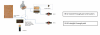
The implementation of the new selector requires a qualified technician that understands the B-2 but the entire process is well documented and has a medium level of difficulty.
Here is an informational video I created as additional support to the written documentation that is provided with the selector kit:
December 2024 Update:
For future iterations, I am considering amending the design and add the ability to couple both inputs, but keeping gain controls just for input #2 .
For inquiries about acquiring the selector board, please use the PM feature.
FILTER CAPS AND FILTER BOARD
Filter Caps:
Should I replace or not?
The answer is a hard YES.
The original Nichicon filter caps were an excellent choice, but these caps are now over 45 years old. Additionally, because of the "oven-like" enclosure where they "live" in, thermal related damage can occur, particularly in the units operated over lengthy periods of time without proper ventilation. As a result, more than two thirds of all the B-2s still functioning today have failing filter capacitors that are either way out of spec or worse: have physically exceeded their functional utility and have leaked dielectric liquid out into the enclosure of the amp. Example below:

Consequently, It is my opinion that every original B-2 needs new filter caps.
What do I replace them with?
Fortunately, Nichicon still offers excellent replacement candidates such as the Gold Tune series Audio rated caps which are some of the best Audio caps ever made. There are also other offerings from Kemet / Riffa and from Epcos / TDK. These are general purpose capacitors with serious performance specs that do make good replacements for the originals.
Filter Caps PCB:
Should I replace or not?
This is not necessary to replace but recommended for ease of installation and for gains in floor noise reduction.
Working with the original PCB: When replacing filter capacitors, one needs to physically alter the original board, which is not very difficult for the Nichicons with standard tabs, but challenging for fitting caps with screw-type terminations.
What can I replace them with?
In order to enhance the ease of filter capacitors replacement and installation I have developed a new filter board design and capitalized on the opportunity to add the following improvements:
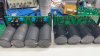

Other AKers have already used this new board for very nice restoration projects:
https://audiokarma.org/forums/index.php?threads/yamaha-b-2-rebuild.1010185/
POWER SUPPLY BOARD
The power supply board is another area that could be improved.

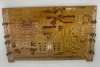
For most of my rebuilds to date, I reused the original PCB and replace very much every component:
Overall, the rebuilt original board with all the above improvements, functions very well. Here is an example of a rebuilt original PSU:


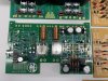
That said, de-soldering components from the original board gets dull over time. This pushed me to the decision to developed a full replacement PCB which addresses all the above named issues plus adds a few additional improvements:
DRIVER BOARD(s)
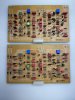
Driver and pre-driver transistors:
Should I replace or not?
The answer is a hard YES. The originals are weak for the job as they operate at the upper end of their SOA.
During post-mortem / retrospective of "dead" B2s, I have seen failed vfets and in some cases all four failed vfets in one channel, where the only other components in that entire driver board that were faulty, were the drivers. I could state with certainty that one of the driver transistors failed and killed the vfets in he process, by cutting off gate supply voltage during operating conditions.
What do I replace them with?
Hopefully with something that's rated for higher collector current / Ic and higher Vce (which would place the the transistor's operating parameters lower in the SOA), but which still has good linearity and a small collector output capacitance (Cob).
The OnSemi KSA1381/KSC3503 and Toshiba TTA004/TTC004 are excellent replacements, are readily available and will improve reliability without impact to sound signature.
Do not stress about perfect matching or not having the same rank. The only pair that needs good matching is the two PNP transistors in the differential pair of the VAS / pre-driver stage, respectively TR107 and TR108.
Fusible resistors:
Should I replace or not?
The answer is YES. The original resistors have no real fusible role. The only role they serve is to prevent fire. Yamaha tells us this clearly in the crappy sticker they attached to the driver boards of the US models...sort of along the lines of the McDonalds warnings: "the coffee is hot and you might burn yourself". Lame but the label is there (US models only) and it blocks the silk screen for the test pins, which is a reason why I religiously remove those stickers. Besides, if one needs to see the sticker to pay attention to what they are doing, perhaps he/she should not be poking underneath the hood of a B2.
Additionally to the fire protection role, and as mentioned above, these resistors play no real fusible role in the circuit. In every failed unit I encountered, I found fried transistors but no fried fusible resistors. Ironically speaking, the fusible resistors were well protected by the failed transistors.
Additionally, the 390ohm 1/4w (R151, R152) do drift generally quite a bit from the original value over time.
What do I replace them with?
HV46R "Double-Diodes":
Should I replace them or not?
My opinion is that there is no supporting evidence that indicates a need to replace.
For the past two-dozen plus B-2 rebuilds so far, I did replace them because of the stigma associated with the version that Sony used,.... the dreaded "Death-Diodes".
However, the version of these "diodes" that Yamaha used do not have a measurable failure rate. By now I have worked in well over two-dozen B-2s and if we consider that each B-2 has 11 x HV46 diodes and none of them I found none that were bad or suspicious even in units with fried vfets, I consider the sample size to be statistically significant and as a result I will no longer replace these diodes in my rebuilds going forward. They are reliable parts.
If I still want to replace, what do I replace them with?
2 X 1N4140, 1N914, etc.
Input differential pair:
Yamaha B-2 uses two Sony 2sk43 j-fets as an input differential pair. These TO-92 devices are positioned face to face and held together by a copper clip. Over time some of these transistors could fail or drift from the original specs and this would usually result in an unstable / drifting DC offset.
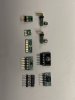
When required, the input differential pair can be replaced with a few modern options from Toshiba, Linear Systems, Vishay and Texas Instruments. All of the modern replacements require some type of adapter. These replacements are all dual transistors on a single chip so they are inherently better for the job then the original, two mechanically attached transistors. I prefer using the Toshiba SoTs because they have very good characteristics and are available with different ranks.
Here are examples of adapters I have developed for B-2, B-3 and other amps:
To be continued in Part Two.
There will be subsequent parts within this thread since there is a limit of how many photos I can attach to each post.
There will be additional edits to this post for both content and syntax.
Abstract:
A fully upgraded B-2 offers a unique opportunity to own a vintage v-fet amplifier with all the modern features and reliability of a new amp. Leveraging today's technical advancements coupled with about 40+ years of data about the B-2, we can now take a great amplifier that is tired with age and return it to prime functionality or make it even better than when it left the factory floor.
The following details about the work I do with the B-2s are intended to share my opinions and experiences to hopefully help answer questions for other B-2 owners.
Some of the topics will involve radical modifications to the original components and / or design. At no point in time I claim that I know more than the Yamaha engineers did ~45 years ago, but merely have the ability to learn from what they have created, observe data collected by me and others over time, leverage the use of advanced computer aided design and better materials available today, to improve from where the Yamaha engineers left off.
WARNING:
- I hope this thread should not give "wings" to dive underneath the hood of B-2 to anyone that should not be there to begin with...
- For those doing their own work: do your own research and you are doing all these at your own risk...The old saying goes, measure twice and cut once applies here: Research, research, then solder or disorder.
- Also for those doing your own work: I hold no responsibility if you brick your B-2, get your house on fire, electrocute yourself, etc.
- Remember that one dead vfet means your B-2 becomes a parts unit as you need a full set of four matched vfets to fix a B-2 with one bad vfet.
- DO NOT TAKE THE RESTORATION OF A B-2 LIGHTLY OR THINK THAT YOU ARE REBUILDING JUST ANOTHER VINTAGE AMPLIFIER.
Disclaimer:
- If you are a Yamaha purist that sees any deviations from the original design as unacceptable, viewer discretion is advised that reading forward might give you nightmares that you would never be able to wipe off of your memory

- If you are here because you own a B-2 and would like to learn more about how to fix it or make it better, but do not have the technical ability to perform the work yourself, state your location and someone here should be able to help you locate a qualified technician near your location.
- If you plan to introduce these mods to a B-2, no hand-holding or spoon-feeding will be provided. This mods require the experience, skillset with working on v-fet amps and the proper tools and instruments, to complete this job.
- Once again, the following are strictly my opinions and choices based on my experience. YMMV.
Below is a High-level list of what I consider areas of opportunity for improvement for the Yamaha B-2 based on the order of importance / level of annoyance or functional criticality.
High importance (i.e. major PITA):
- Selector board assembly
- Filter caps
- Power Supply
- Driver boards
- Speaker posts
- Power Switch
Miscellaneous (nice to have):
- Wire harness management
- Vu-Meter board
- Chassis
- Vu-Meter input selector bi-pass (amended 11/27/2024)
I intend to organize the order of topics aligned with the above priority list. Until I find the time to add details about each topic, the information below might seem uncoordinated with the list above, but it will eventually make sense once I am done adding and editing everything.
SELECTOR ASSEMBLEY
The selector assembly is a pain-point reported by most Yamaha B-2 owners and for this reason it makes the top of the priority list for improvements.
Unfortunately, simply cleaning the original selector switches does not solve the issues every Yamaha B-2 suffers from. This is because the open air switches that are exposed to undesirable elements, operate signal and VDC within the same switch unit. Even minor smoke and moisture deposits can create grime buildup which in-turn can become conductive and bring DC in the signal path, causing POPs and crackles when operating the switches. Additionally, oxidation of the now 45+ years old contacts provides less than ideal contact, rubbing away some of the B2's magical sound. Unfortunately, when improperly cleaned with abrasive materials by novice technicians or weekend warriors, the silver plating of the original contacts gets permanently damaged and this is actually a very common problem.
In order to permanently correct the selector assembly issues, I have developed a new assembly board with functionality that is transparent to the user but that it is technically much more superior and more reliable than the original design. This is because in the newly redesign selector the mechanical switches do not handle signal switching. The signal switching is handled by state-of-the-art sealed relays that are operating well below their rated specs, hence are expected to easily exceed the reliability of the original design.
Under the new design, the signal integrity is preserved as is the consistency of the functionality of the switching assembly. As a result, the redesigned functional utility is better than when the B-2 was brand new.
There are some operational differences between the original B-2 functions, as follows:
- The rear input #1 is now a direct path to the driver boards. This is function that most audiophiles prefer, in order to take full advantage of the DC design of the B-2. The downside of this feature is that a DC leaky preamp could destroy the B-2.
- The rear input #2 preserves all the original functionality, allowing for capacitor coupling and gain control, just as the original design did. However, the coupling capacitors used are good quality polypropylene caps, much better then the original tantalum caps. The pots I use are dual 50Kohm pots mounted in parallel to preserve the original 25Kohm input impedance of the B-2. The reason for the dual-pots is because they are a readily available part and because the two plastic retainers inside the pot are better than one plastic retainer inside the single original pot, which breaks easily and it is an annoyance for many B-2 owners.
The implementation of the new selector requires a qualified technician that understands the B-2 but the entire process is well documented and has a medium level of difficulty.
Here is an informational video I created as additional support to the written documentation that is provided with the selector kit:
December 2024 Update:
For future iterations, I am considering amending the design and add the ability to couple both inputs, but keeping gain controls just for input #2 .
For inquiries about acquiring the selector board, please use the PM feature.
FILTER CAPS AND FILTER BOARD
Filter Caps:
Should I replace or not?
The answer is a hard YES.
The original Nichicon filter caps were an excellent choice, but these caps are now over 45 years old. Additionally, because of the "oven-like" enclosure where they "live" in, thermal related damage can occur, particularly in the units operated over lengthy periods of time without proper ventilation. As a result, more than two thirds of all the B-2s still functioning today have failing filter capacitors that are either way out of spec or worse: have physically exceeded their functional utility and have leaked dielectric liquid out into the enclosure of the amp. Example below:
Consequently, It is my opinion that every original B-2 needs new filter caps.
What do I replace them with?
Fortunately, Nichicon still offers excellent replacement candidates such as the Gold Tune series Audio rated caps which are some of the best Audio caps ever made. There are also other offerings from Kemet / Riffa and from Epcos / TDK. These are general purpose capacitors with serious performance specs that do make good replacements for the originals.
Filter Caps PCB:
Should I replace or not?
This is not necessary to replace but recommended for ease of installation and for gains in floor noise reduction.
Working with the original PCB: When replacing filter capacitors, one needs to physically alter the original board, which is not very difficult for the Nichicons with standard tabs, but challenging for fitting caps with screw-type terminations.
What can I replace them with?
In order to enhance the ease of filter capacitors replacement and installation I have developed a new filter board design and capitalized on the opportunity to add the following improvements:
- Multi-type mounting options for both, tabs and screw terminals. Other mounting formats such as for those caps with 4 or 5-prongs were considered but ultimately decided against because there are no quality capacitors made today with 5-prongs, other then cheap quality SMPS type caps which would make the B-2 sound like crap.
- Eliminated the need for jumper wires (which were wimpy sized IMHO), by leveraging a double-sided PCB.
- Optimized the center ground paths to properly branch out to the speaker output and the ancillary circuits of the amp.
- Replace the regular rectifier diodes with state-of-the-art, new soft recovery diodes for lower noise gains.
- Added RC snubber networks to reduce residual transformer ringing (transformer ringing is already drastically reduced by using soft-recovery diodes).
Other AKers have already used this new board for very nice restoration projects:
https://audiokarma.org/forums/index.php?threads/yamaha-b-2-rebuild.1010185/
POWER SUPPLY BOARD
The power supply board is another area that could be improved.
- The original phenolic type PCB is weak for the weight it needs to support and it sags,
- The way the mechanical design was implements, transforms this PCB into an "oven - like" lead, trapping heat / preventing proper ventilation. This slowly cooks the "enclosed" components with the big cans and other small lyrics being primarily of concern.
- Sony corrosive glue used to mechanically attach the regulator transistors to the PCB was a horrible idea. Besides that it is corrosive, has poor thermal and mechanical properties. It is very rare when I find a heatsink that it is still properly attached.
- The power resistors are mounted too close to the board and scorch the PCB, sometimes quite severely, particularly if the B-2 was sues in an enclosed space without proper ventilation.
- The use of jumpers and the way the traces are laid out in this board, particularly in the path to the speakers circuit, it is not ideal.
For most of my rebuilds to date, I reused the original PCB and replace very much every component:
- all semiconductors for either being known to be ill-fated or for having oxidized / black legs
- All lytics replaced with higher rated temperature version and in most cases with higher rated voltage.
- All carbon film resistors with metal film, low PPM type. Metal film resistors are a great choice here because they have less thermal runaway and have better noise properties.
- The power resistors are mounted above the board a few millimeters so they no longer scorch the board.
- The heatsinks for the three regulator transistors get reattached with high temp rating two part epoxy (non inductive). Silicon could also be used but it is messy.
Overall, the rebuilt original board with all the above improvements, functions very well. Here is an example of a rebuilt original PSU:
That said, de-soldering components from the original board gets dull over time. This pushed me to the decision to developed a full replacement PCB which addresses all the above named issues plus adds a few additional improvements:
- saggy original board -> the new board is 2mm thick FR4 PCB
- heat trap -> implemented multiple cutouts at each location of the power resistors, TO-220 heatsinks and outside perimeter
- mechanical attachment for the heatsinks -> new solder style mount heatsinks
- circuit layout -> optimized circuit layout by leveraging the two-sided PCB to eliminate jumpers and to optimize tracks' length.
DRIVER BOARD(s)
Driver and pre-driver transistors:
Should I replace or not?
The answer is a hard YES. The originals are weak for the job as they operate at the upper end of their SOA.
During post-mortem / retrospective of "dead" B2s, I have seen failed vfets and in some cases all four failed vfets in one channel, where the only other components in that entire driver board that were faulty, were the drivers. I could state with certainty that one of the driver transistors failed and killed the vfets in he process, by cutting off gate supply voltage during operating conditions.
What do I replace them with?
Hopefully with something that's rated for higher collector current / Ic and higher Vce (which would place the the transistor's operating parameters lower in the SOA), but which still has good linearity and a small collector output capacitance (Cob).
The OnSemi KSA1381/KSC3503 and Toshiba TTA004/TTC004 are excellent replacements, are readily available and will improve reliability without impact to sound signature.
Do not stress about perfect matching or not having the same rank. The only pair that needs good matching is the two PNP transistors in the differential pair of the VAS / pre-driver stage, respectively TR107 and TR108.
Fusible resistors:
Should I replace or not?
The answer is YES. The original resistors have no real fusible role. The only role they serve is to prevent fire. Yamaha tells us this clearly in the crappy sticker they attached to the driver boards of the US models...sort of along the lines of the McDonalds warnings: "the coffee is hot and you might burn yourself". Lame but the label is there (US models only) and it blocks the silk screen for the test pins, which is a reason why I religiously remove those stickers. Besides, if one needs to see the sticker to pay attention to what they are doing, perhaps he/she should not be poking underneath the hood of a B2.
Additionally to the fire protection role, and as mentioned above, these resistors play no real fusible role in the circuit. In every failed unit I encountered, I found fried transistors but no fried fusible resistors. Ironically speaking, the fusible resistors were well protected by the failed transistors.
Additionally, the 390ohm 1/4w (R151, R152) do drift generally quite a bit from the original value over time.
What do I replace them with?
- Since we want to avoid any potential fires, we need to look for metal film or resistors with fire proof coating.
- We want to replace with the same wattage rating as the originals.
- Since some of these resistors are placed directly in the signal path, we want good noise performance ratings.
- Vishay has great candidates for this role, such as the RN series.
HV46R "Double-Diodes":
Should I replace them or not?
My opinion is that there is no supporting evidence that indicates a need to replace.
For the past two-dozen plus B-2 rebuilds so far, I did replace them because of the stigma associated with the version that Sony used,.... the dreaded "Death-Diodes".
However, the version of these "diodes" that Yamaha used do not have a measurable failure rate. By now I have worked in well over two-dozen B-2s and if we consider that each B-2 has 11 x HV46 diodes and none of them I found none that were bad or suspicious even in units with fried vfets, I consider the sample size to be statistically significant and as a result I will no longer replace these diodes in my rebuilds going forward. They are reliable parts.
If I still want to replace, what do I replace them with?
2 X 1N4140, 1N914, etc.
Input differential pair:
Yamaha B-2 uses two Sony 2sk43 j-fets as an input differential pair. These TO-92 devices are positioned face to face and held together by a copper clip. Over time some of these transistors could fail or drift from the original specs and this would usually result in an unstable / drifting DC offset.
When required, the input differential pair can be replaced with a few modern options from Toshiba, Linear Systems, Vishay and Texas Instruments. All of the modern replacements require some type of adapter. These replacements are all dual transistors on a single chip so they are inherently better for the job then the original, two mechanically attached transistors. I prefer using the Toshiba SoTs because they have very good characteristics and are available with different ranks.
Here are examples of adapters I have developed for B-2, B-3 and other amps:
To be continued in Part Two.
Last edited: