

You are using an out of date browser. It may not display this or other websites correctly.
You should upgrade or use an alternative browser.
You should upgrade or use an alternative browser.
Yamaha B2 - the "why" and the "how" of a comprehensive rebuild
- Thread starter rottalpha
- Start date
-
- Tags
- v-fet yamaha b-2


Yes indeed and the subject for another thread since this one is about Rott's comprehensive rebuild.But that would a pity wouldn't it?

To be continued in Part Three

Last edited:

Pete, are you going to add the voltage checks at critical points that need to be verified before re-installation of the V-fets after doing all of the above maintenance ?
I remember the anxiety I had before firing up my B-2 after the refurb I did in 2020 . Even after I found a post with he voltages needed at the V-fet board.
Athanasios
I remember the anxiety I had before firing up my B-2 after the refurb I did in 2020 . Even after I found a post with he voltages needed at the V-fet board.
Athanasios

I have to think about that. When I hear of vfets being destroyed, I am questioning if documenting the rebuild is a good or a bad thing.....i.e. a false sense of confidence is not good when working on vfet amps....fill in the blanks..Pete, are you going to add the voltage checks at critical points that need to be verified before re-installation of the V-fets after doing all of the above maintenance ?
I remember the anxiety I had before firing up my B-2 after the refurb I did in 2020 . Even after I found a post with he voltages needed at the V-fet board.
Athanasios
I have to think about that. When I hear of vfets being destroyed, I am questioning if documenting the rebuild is a good or a bad thing.....i.e. a false sense of confidence is not good when working on vfet amps....fill in the blanks..
Yep I understand this totally . That is why I asked if it would be included.
Personally I feel its a good thing for those who have experience and are methodical in rebuilding vintage audio gear, even though a V-fet is a whole other animal due to the rarity of the output devices.Even though they may know themselves what the proper voltages and points may be it be good for them to have a reference to double check incase they have an occasional brain fart of that info.
Maybe a warning for those who are a bit timid that they should refrain from doing the rebuild themselves .
Athanasios
Part Three (make sure you read Part One and Part Two first).
In this part I will be describing "NICE TO HAVE" improvements.
WARNING:
In the quest to reduce picking up as little EMI and mains noise as possible, we need to make improvements to the wire harness so that lengthy runs do not act as mini-antennas and located as far away from mains AC lines.
Twist those transformer wires...For later units Yamaha made sure to twist the wire harness where applicable. For B2 not so much.
I personally like to twist the transformer wires since I need to remove then and re-solder them back for any rebuild. It does not take too much time to do it:
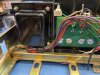
VS


Move those AC lines away from the audio path
The rear inner support plate is actually an additional metal shield against the transformers electromagnetic field emissions and should technically also help separate the AC lines from the audio path such as the speaker wires, yet the AC wires are not optimally managed, particularly in newer serial numbers B-2s where Yamaha moved the fuse holders from the rear vertical mount to top of the capacitors in a horizontal mount with the AC mains lines near the rear signal input board and literally touching the speaker wires. This is a bit of a puzzle for me. Sony took the separation of power cables from signal path cables a bit more serious. Yamaha did the same for later units but not so much for the B-2.

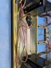
Since in most cases we need to install taller filter caps, we have one additional reason to move the wire harness away from the center section as the original harness is in the way of taller filter caps. For better separation I prefer to run the AC transformer feeds underneath the chassis to clear the taller caps and to keep the AC wires away from the audio section as much as possible.

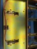
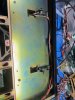
If one wants to get really fancy about this, the entire fuse holder assembly and AC wire harness can be moved on the bottom of the chassis.
Next:
VU-METER AMP BOARD
CHASSIS
In this part I will be describing "NICE TO HAVE" improvements.
WARNING:
- I hope this thread should not give "wings" to dive underneath the hood of B-2 to anyone that should not be there to begin with...
- For those doing their own work: do your own research and you are doing all these at your own risk...The old saying goes, measure twice and cut once...same applies here: Research, research, then solder or disorder.
- Also for those doing your own work: I hold no responsibility if you brick your B-2, get your house on fire, electrocute yourself, etc.
- One dead vfet means your B-2 becomes a parts unit as you need a full set of four matched vfets to fix a B-2 with one bad vfet.
- DO NOT TAKE THE RESTORATION OF A B-2 LIGHTLY OR THINK THAT YOU ARE REBUILDING JUST ANOTHER VINTAGE AMPLIFIER.
In the quest to reduce picking up as little EMI and mains noise as possible, we need to make improvements to the wire harness so that lengthy runs do not act as mini-antennas and located as far away from mains AC lines.
Twist those transformer wires...For later units Yamaha made sure to twist the wire harness where applicable. For B2 not so much.
I personally like to twist the transformer wires since I need to remove then and re-solder them back for any rebuild. It does not take too much time to do it:
VS
Move those AC lines away from the audio path
The rear inner support plate is actually an additional metal shield against the transformers electromagnetic field emissions and should technically also help separate the AC lines from the audio path such as the speaker wires, yet the AC wires are not optimally managed, particularly in newer serial numbers B-2s where Yamaha moved the fuse holders from the rear vertical mount to top of the capacitors in a horizontal mount with the AC mains lines near the rear signal input board and literally touching the speaker wires. This is a bit of a puzzle for me. Sony took the separation of power cables from signal path cables a bit more serious. Yamaha did the same for later units but not so much for the B-2.
Since in most cases we need to install taller filter caps, we have one additional reason to move the wire harness away from the center section as the original harness is in the way of taller filter caps. For better separation I prefer to run the AC transformer feeds underneath the chassis to clear the taller caps and to keep the AC wires away from the audio section as much as possible.
If one wants to get really fancy about this, the entire fuse holder assembly and AC wire harness can be moved on the bottom of the chassis.
Next:
VU-METER AMP BOARD
CHASSIS
Last edited:
I replace all semis because even if they still work, most of them have black legs. It is rare that I keep any and in those rare occasions they have to be in very good shape. I never reuse the drivers or the VAS transistors.Question about Drive Boards.
Do you only change the 8 Pre Drive and Drive tranny's or all the tranny's on the board?
From the pics it is hard to tell if the other small transistors are replaced.
Athanasios
Last edited:
I replace all semis because even if they still work, most of them have black legs. It is rare that I keep any and in those rare occasions they have to be in very good shape. I never reuse the drivers or the VAS stage transistors.
Would these be good replacements ?

I feel sorry for all the people that owned B2's through the ages and used thin speaker wire. The way speaker wire is reviewed today one would think that the magic of the B-2 would have never gotten to the speakers. They would have missed out on:
"dynamic contrast, transient response, and bass slam that are rendered seemingly without effort" and they would have missed out on "dynamic punch and rhythmic drive", "sheer energy and attack", "large-scale dynamics" and "authority" etc. etc.
Ok, seriously, nice work. And even though your other improvements are much more technical and complicated than speaker binding posts it's nice to be able to use banana plugs, spades and lower gauge speaker wire on vintage amps like this.
Good speaker wires can be used with the original connectors if the original holes are enlarged. The grip of the original speaker posts is actually very good....just PITA to work with. The most important quality of a good speaker wire is that it is as short as possible. Everything else is secondary and yes lots of snake oil BS with speaker wires today and some speaker wire prices getting more expensive than some good amplifiers.
It would have to be from a B-2 not from a B-3 as there is no guarantee that the B-3 vfets are matched well among the channels. Remember, B3 is half of a B2 as in only has two vfets per channel.The other option is to source another b2 or b3 and butcher one of than, But that would a pity wouldn't it?
Last edited:
Another question, Since I rebuilt most of this B2 except for the resistors and transistors on the drive board when setting the Bias and DC offset should I just leave the
trim pots at where they are now? These were changed over in 2020 during the first rebuild .
Also for future readers, and myself, is there a general resistance setting for the trimpots to be at before freeing the unit up if the originals , let say, have wonky readings when trying to replace them and you can not trust what they are?
Athanasios
trim pots at where they are now? These were changed over in 2020 during the first rebuild .
Also for future readers, and myself, is there a general resistance setting for the trimpots to be at before freeing the unit up if the originals , let say, have wonky readings when trying to replace them and you can not trust what they are?
Athanasios
@rottalpha the drive board has a few of those flat "Chicklet" type resistors that cause noise issues in the C2 series pre amps. Should those also be changed?
The Schematic has them listed as Metal Oxide Film resistors .
Athanasios
The Schematic has them listed as Metal Oxide Film resistors .
Athanasios
no metal oxide resistors on the amp boards@rottalpha the drive board has a few of those flat "Chicklet" type resistors that cause noise issues in the C2 series pre amps. Should those also be changed?
The Schematic has them listed as Metal Oxide Film resistors .
Athanasios
no metal oxide resistors on the amp boards

They use a Black triangle to designate them.

and here in this snippet of the schematic for the drive board there are some resistors there
with the Black triangle next to them. Most also have an (F) next to the value. Metal Oxide FILM

What does that mean?
Those are metal film (not metal oxide) likely 1% and low noise. I never found one of these out of spec or fried.They use a Black triangle to designate them.
and here in this snippet of the schematic for the drive board there are some resistors there
with the Black triangle next to them. Most also have an (F) next to the value. Metal Oxide FILM
What does that mean?
Yamaha schematic was never updated. There is more than one error in that schematic.
Last edited:
Thanks Pete, just wanted some clarity .
Nashou
