
Mule goes to 140 @ 8R just like the rebuilds.
@Vint Age I guess Pete can tolerate at least some risk. I guess since its only two sets of B-2 V-fets at risk its ok

Athanasios


Mule goes to 140 @ 8R just like the rebuilds.

Agreedy ... I mean agreed.@Vint Age I guess Pete can tolerate at least some risk. I guess since its only two sets of B-2 V-fets at risk its ok
Exactly what I said back in the day in 1978 when I first got to listen to it as a young Yamaha and others warranty tech; oh how I wished I could have brought one of those beauties home with me back then.The B-2 when it was new was no slouch.
Understood and appreciated!but do not expect it to be too far off.
To my thinking a messy bench is a happy bench and if you tidy up too much you'll never be able to find anything.I need to tidy up my bench a bit and will get some footage in a few...
To my thinking a messy bench is a happy bench and if you tidy up too much you'll never be able to find anything.


To be a fair and honest assessment of an "as is" amp, I think all switches and pots would have to be cleaned, relay contacts cleaned (as long as not burned) and offset, voltage and bias should be set to spec. Basically, a factory adjusted amp working as designed, with all original components (or at least what it came in with) and no modifications. Trouble is, just to get an amp to that point can be a lot of work and you'd end up doing some of the work twice. I doubt too many amps would come in for service ready to go under test and as already said, pushing an "as is" amp to its limits for testing could be dangerous for the amp. Most would probably fail miserably in "as is" condition.
@Vint Age I guess Pete can tolerate at least some risk. I guess since its only two sets of B-2 V-fets at risk its ok
Agreedy ... I mean agreed.
lol
Yours isn’t far away from that bench.WOW , now that is impressive Pete!!
Great explanation and description of what you were trying to accomplish and measure.
I wish I could have hear these back then when my ears were better than they are now .
PS: is that new switch board one mine in the back ground ?
Athanasios
thank you DanI like and agree with your reliability parts changes on your "stock" reference amp, parts changed were kept to a minimum and only for ensuring it doesn't self destruct. Nice video too.
Thanks for that awesome comparison videos! Wish I had an analyzer like that on my bench. Before I retired the company I work for had 2 Audio Precision Analyzers for factory testing in both the analog and digital domain. I wanted to bring my B-2 in for similar testing to yours but the test manager was too paranoid due to their cost so it never happened.take a look and let me know your thoughts:

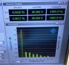
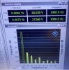


In this case they were both set at about 40mv for this exercise purpose.
Side note: can you say B-1 bias balance
Understood and appreciated!Side note: can you say B-1 bias balance
Side note: can you say B-1 bias balance
Understood and appreciated!

Believe me, that's a whole other thread.Umm..... Ok what do I need to know once I begin work on my B1 ?
Believe me, that's a whole other thread.